
A duct type cooling frequency conversion unit and its layout
A technology of frequency conversion unit and layout method, which is applied in the direction of air cooling, engine cooling, cooling/ventilation device, etc., which can solve the problems of unseen, poor cooling effect of engine and muffler, etc., and achieve weight reduction, good cooling effect, and small size Effect
Patent Information
- Authority / Receiving Office
- CN · China
- Patent Type
- Patents(China)
- Current Assignee / Owner
- Publication Date
- 2021-04-27
Smart Images
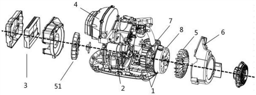
Figure 1 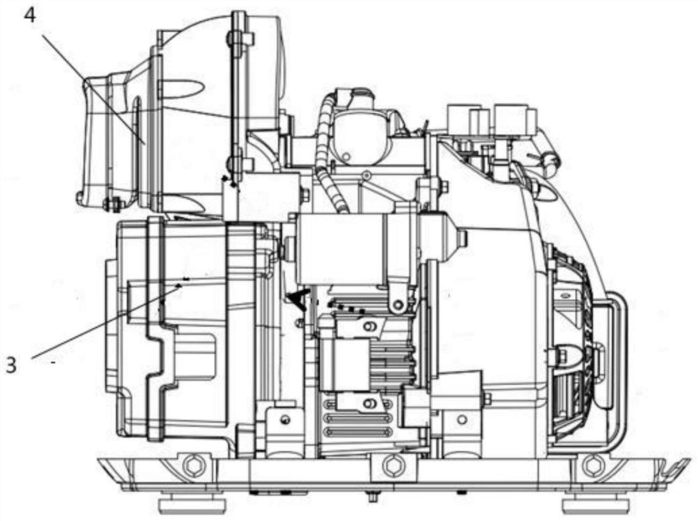
Figure 2 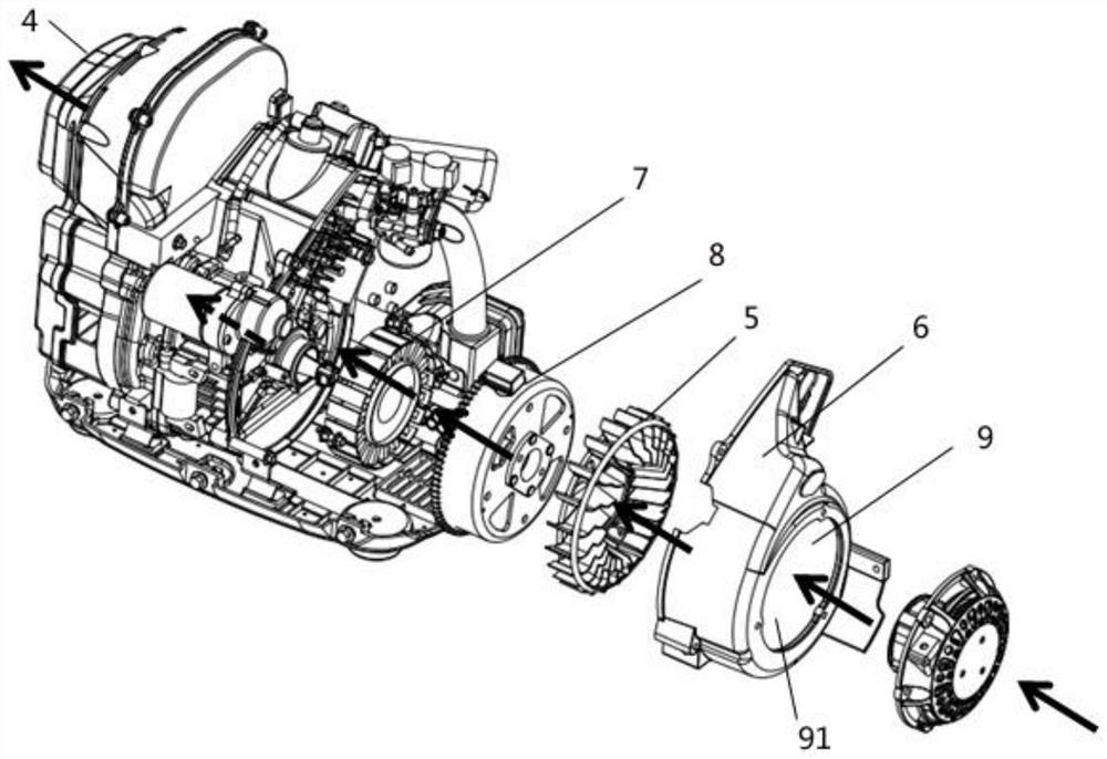
Figure 3
Abstract
Description
technical field
[0001] The invention relates to the technical field of frequency conversion units, in particular to an air duct cooling frequency conversion unit and its layout. Background technique
[0002] With the rapid development of the economy and the improvement of people's living standards; as a kind of emergency power supply - variable frequency generators are becoming more and more popular. However, there are following defects and deficiencies in the frequency conversion generator in the prior art:
[0003] First of all, regarding the structure, in the frequency conversion generator set in the prior art, the generator is installed below the muffler. The inverter is installed at the outer end. In order to ensure the stability of the engine speed and achieve the purpose of controlling the smooth operation of the engine, the flywheel is made of cast iron in a solid disc shape, which makes the size of the flywheel larger, the size of the whole machine is larger, and ...
Examples
Embodiment 1
[0049] Please refer to figure 1 with figure 2 , figure 1 Schematic diagram of the explosion structure of the frequency conversion unit of the present invention. figure 2 It is a schematic diagram of the general assembly structure of an air duct cooling frequency conversion unit of the present invention. An air duct cooling frequency conversion unit, the air duct cooling frequency conversion unit includes a generator 1, an engine 2, an inverter 3, and a muffler 4; the generator 1 is installed at one end away from the muffler 4; the An engine 2 is installed on one side of the generator 1; an inverter 3 is installed on one side of the engine 2; the inverter 3 is installed at a position with the lowest temperature from the muffler 4, and the inverter 3 is installed on the muffler 4 below.
[0050] What needs to be explained in this embodiment is:
[0051] In this embodiment, the generator 1 includes a stator 7 and a rotor 8. The installation of the stator 7 and the rotor 8 ...
Embodiment 2
[0058] Please refer to Figure 3-Figure 5 , image 3 It is a schematic diagram of the distribution direction of the first air duct 9. Figure 4 It is a schematic diagram of the distribution direction of the second air duct 10 . Figure 5 It is a schematic diagram of the air duct distribution of the frequency conversion unit. A layout of the air duct cooling frequency conversion unit, the layout includes a first air duct 9 and a second air duct 10; the first air duct 9 flows into the generator 1 through the first air inlet 91, cooling The generator 1 enters the engine 2, then cools the engine 2, enters the muffler 4 after cooling the engine 2, and discharges the muffler 4 after being cooled; the second air inlet channel flows in from the second air inlet 101 and is cooled Afterwards, the inverter 3 merges with the first air channel 9 and flows out of the muffler 4 .
[0059] What needs to be explained in this embodiment is:
[0060] The layout of the entire frequency conve...
Embodiment 3
[0064] Please refer to Image 6 with Figure 7 , Image 6 It is a schematic diagram of the air duct distribution trend in Embodiment 3. Figure 7 It is the side air intake schematic diagram in embodiment 3. This embodiment is basically the same as Embodiment 2, except that a third air duct 11, a third air inlet 111, and an air inlet duct 12 are provided in this embodiment; the third air inlet 111 is directed toward the bottom of the machine side, the cooling air of the third air inlet 111 is divided into two paths, one path merges with the first air inlet 91 and flows into the first air duct 9, and the other path passes through the base of the engine 2 to dissipate heat, then enters the air inlet duct 12 and flows through the muffler 4 flow out.
[0065] What needs to be explained in this embodiment is:
[0066] The third air inlet 111 faces the bottom of the machine, and this design method has the effect of dust removal and noise reduction; the cooling air of the third a...