
Novel forging equipment
A new type of equipment and technology, applied in the field of forging, can solve the problems of high maintenance rate of forging manipulators, damage of forging manipulators, short service life, etc., and achieve the effect of preventing rigid contact, ensuring forging quality, and preventing movement.
Patent Information
- Authority / Receiving Office
- CN · China
- Current Assignee / Owner
- Publication Date
- 2019-07-05
Smart Images
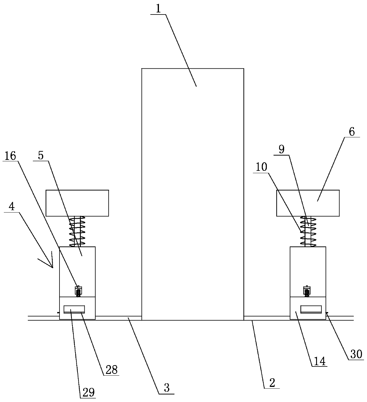
Figure 1 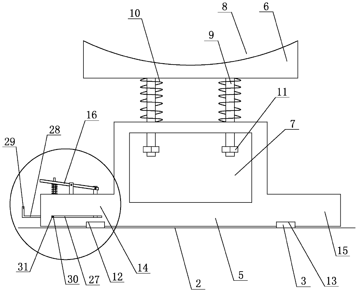
Figure 2 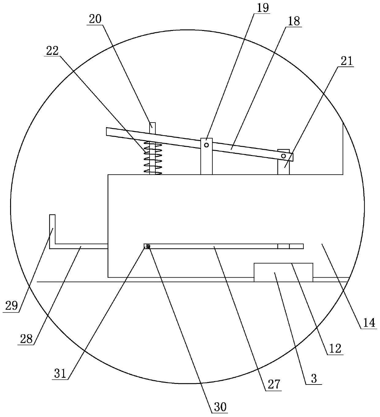
Figure 3
Abstract
Description
technical field
[0001] The invention relates to the field of forging, in particular to a novel forging equipment. Background technique
[0002] In the prior art, when forging long-sized products, because the size of the forging equipment is limited, when forging, generally, partial forging is performed first, that is, a part of the product is placed in the forging machine for forging. After this part of forging is completed, the product is moved. Insert the unforged place into the forge for forging. In this process, the parts inside the forging machine are supported by the forging machine, while the products outside the forging machine are supported by the forging manipulator. However, during the forging process, the forging part will sink, that is, it will drive the products outside the forging machine to sink, so the momentary sinking of the momentum will cause great damage to the forging manipulator. The maintenance rate of the forging manipulator is high and the servi...
Examples
Embodiment 1
[0024] Embodiment one: see Figure 1~5 As shown, a new type of forging equipment includes a forging machine 1, the forging machine 1 is installed on the ground 2, slide rails 3 are respectively provided on the ground on both sides of the forging machine 1, and the slide rails 3 on both sides A support mechanism 4 is respectively slidably provided, and the support mechanism 4 includes a base 5 and a support block 6 arranged on the top of the base 5. The bottom surface of the base 5 is provided with two mutually parallel slide grooves, and the base 5 Slidingly arranged on the slide rail 3 through the chute; a cavity 7 is provided in the middle of the base 5, and two first through holes are provided on the top surface of the base 5, and the two first through holes The hole communicates with the cavity 7, the top of the support block 6 is provided with an arc-shaped opening 8, and the bottom of the support block 6 is provided with two guide rods 9, and the bottoms of the two guide...