
Unmanned aerial vehicle self-active platform take-off and landing auxiliary device
An auxiliary device and unmanned aerial vehicle technology, which is applied to ground devices, landing gear, aircraft parts, etc., can solve the problems of poor battery life and inability to provide global information on the water surface for a long time, and achieve the effect of good stability and accurate control methods.
Patent Information
- Authority / Receiving Office
- CN · China
- Current Assignee / Owner
- Publication Date
- 2019-07-12
Smart Images
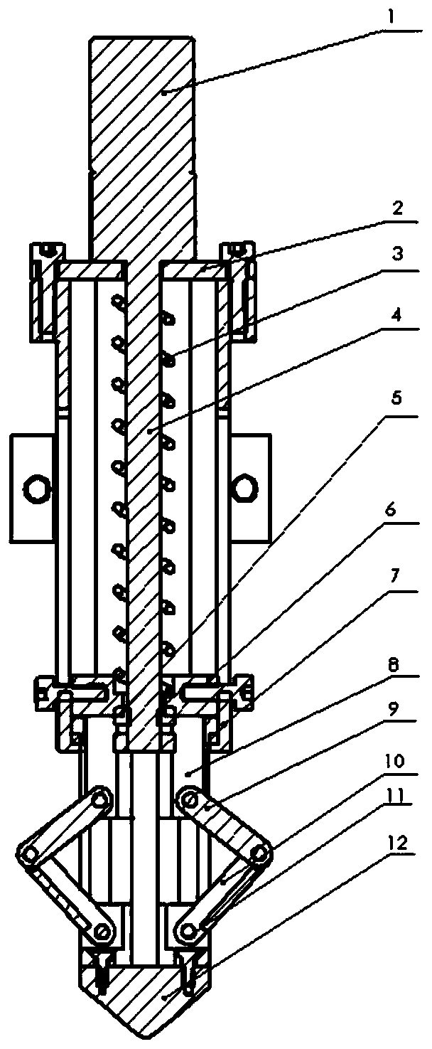
Figure 1 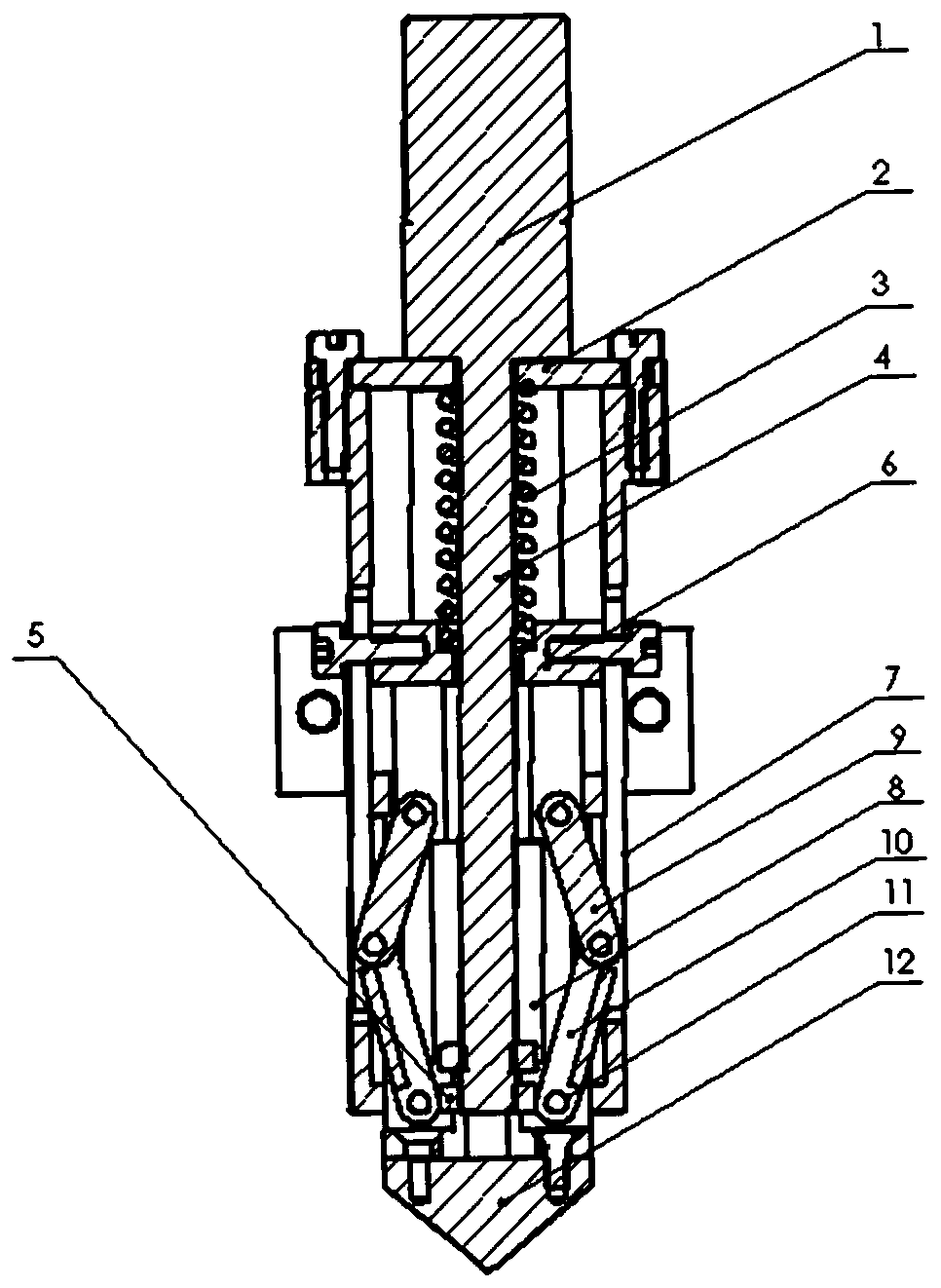
Figure 2 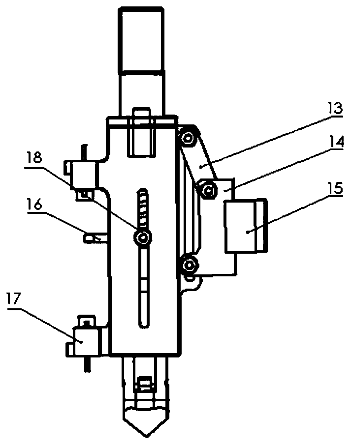
Figure 3
Abstract
Description
technical field
[0001] The invention belongs to the field of cooperation between unmanned aerial vehicles and unmanned ships, and specifically provides an auxiliary device for taking off and landing on an autonomous platform of an unmanned aerial vehicle. Background technique
[0002] Among the current problems in the development of robotic equipment, the endurance of drones and the narrow field of view of unmanned ships have been hindering further research. UAVs have a wide field of view but poor battery life, and cannot provide global information on the water surface for a long time; unmanned ships have insufficient ability to perceive the water surface environment, but have strong battery life. Wide field of vision perception and the realization of autonomous take-off and landing of drones are the key to combining them. Therefore, there is an urgent need for a more complete robot collaboration system. Contents of the invention
[0003] In order to overcome the shortco...
Examples
Embodiment
[0036] Such as figure 1 , figure 2 As shown, this embodiment provides an auxiliary device for unmanned aerial vehicle self-active platform take-off and landing, including: DC geared motor 1, compression spring 3, DC geared motor screw 4, motor slider 5, rectangular slider 6, rectangular sleeve 7. Front fork 8, connecting rod 9, stop arm 10 and torsion spring 11;
[0037] In this embodiment, the top of the rectangular sleeve 7 is provided with a rectangular sleeve top cover 2, and the bottom is provided with a harpoon structure protruding hole, and the DC geared motor 1 is fixedly installed on the rectangular sleeve top cover 2. The compression spring 3, the rectangular slider 6 and the harpoon structure are sequentially placed in the rectangular sleeve 7 from top to bottom, and the rectangular sleeve 7 is provided with a through hole, so that one end of the DC geared motor screw 4 is arranged in the rectangular sleeve, The DC geared motor screw 4 is connected to the harpoon...