
Rotor engine internal ignition device
A rotary engine and ignition device technology, applied in engine ignition, engine components, combustion engines, etc., to achieve the effects of reducing emissions, fully burning fuel, and improving performance
Patent Information
- Authority / Receiving Office
- CN · China
- Current Assignee / Owner
- Publication Date
- 2019-07-12
Smart Images
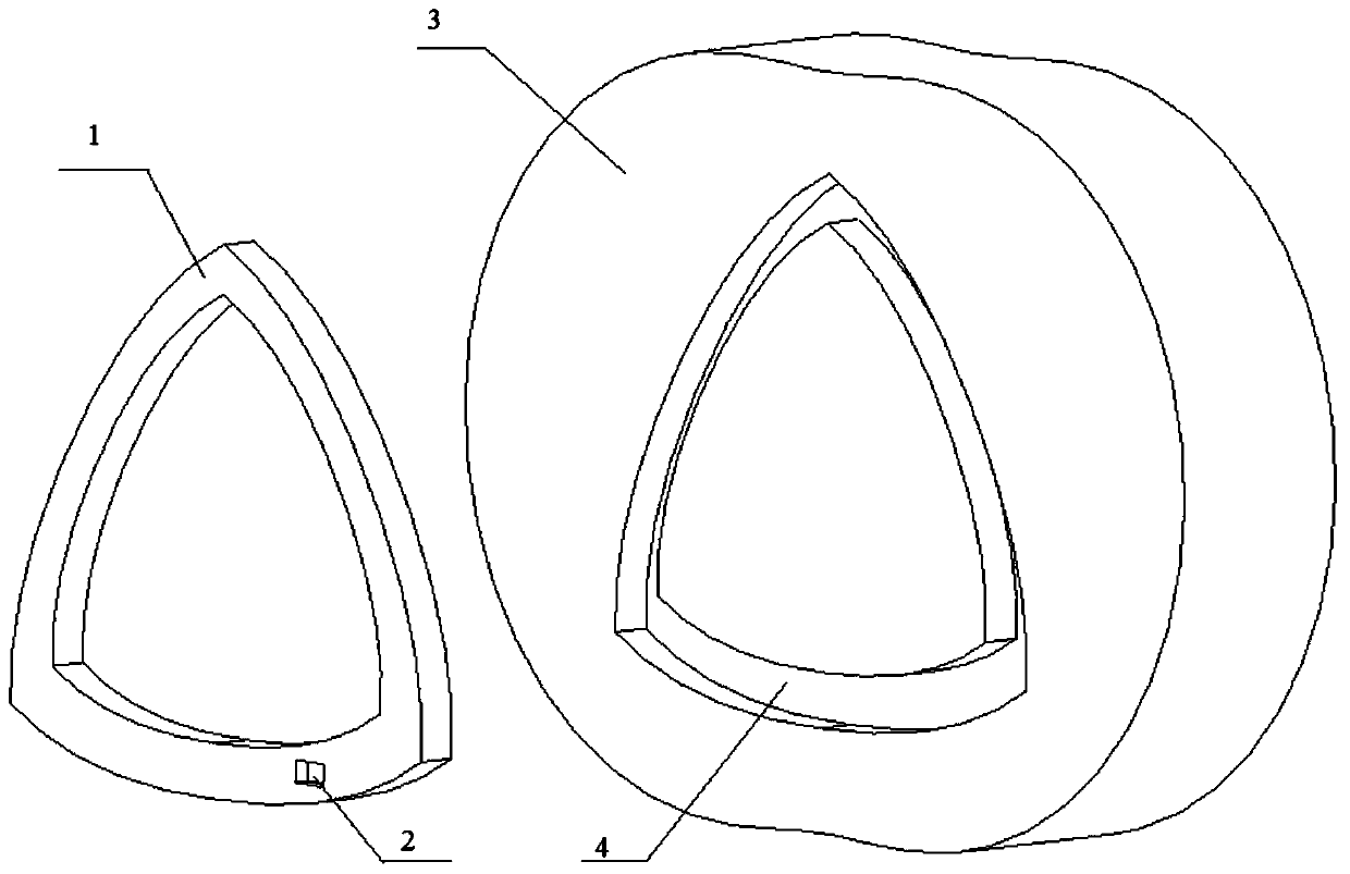
Figure 1 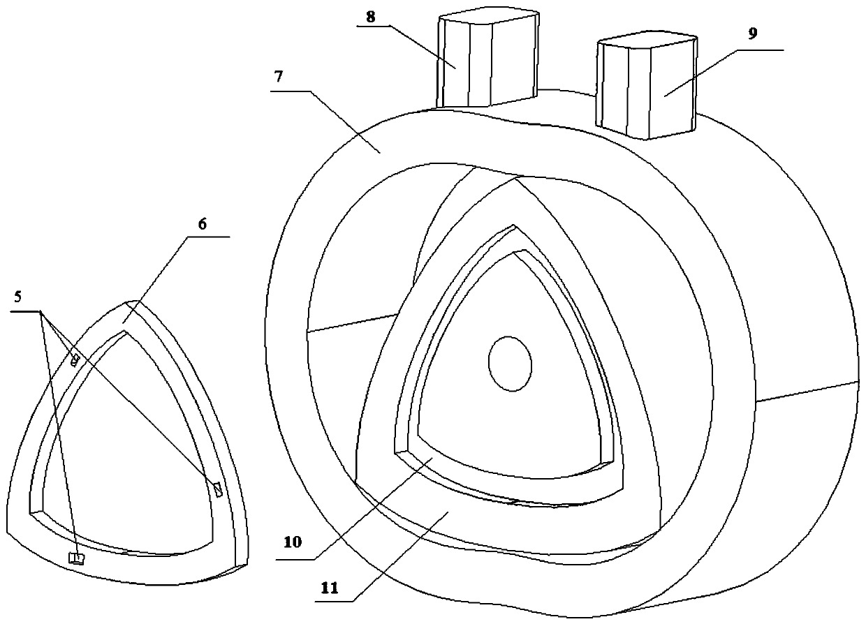
Figure 2 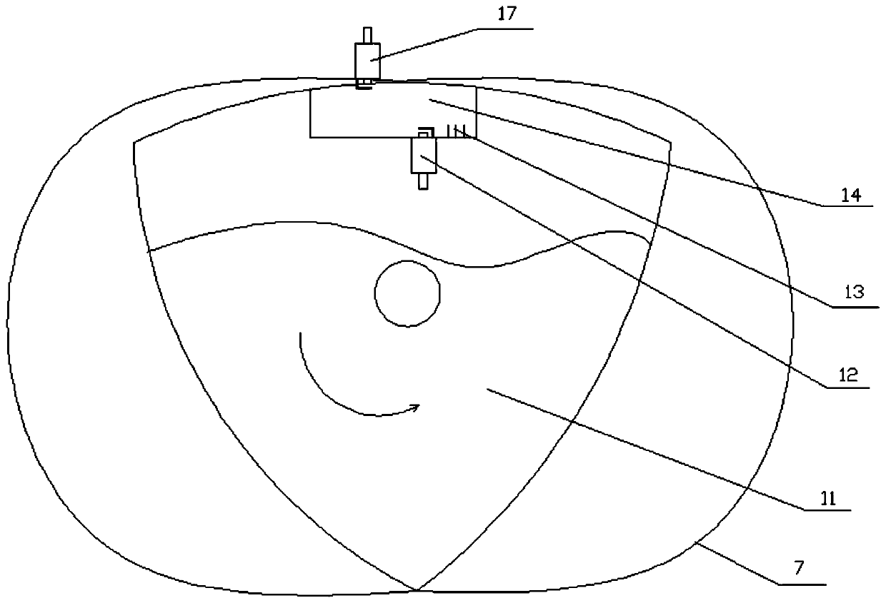
Figure 3
Abstract
Description
technical field
[0001] The invention relates to the field of rotary engines, in particular to an ignition device inside the rotary engine. Background technique
[0002] In the field of internal combustion engines, the energy of fuel combustion will be converted into: external work, vaporization potential and various heat losses, so the fuel cannot be completely converted into external work. How to convert fuel into external work as much as possible has become one of the goals of internal combustion engine designers. For internal combustion engines, incomplete combustion will make the engine work unstable, the output power will decrease, and it will cause serious emission exceeding the standard, and even cause damage to the catalytic converter. The degree of complete combustion of internal combustion engine fuel directly affects the amount of heat generated and the composition of exhaust gas, and the timing of combustion is related to the degree of heat utilization. Therefo...
Examples
Embodiment 1
[0027] Embodiment 1, the energization device includes a first conductive device and a second conductive device, the second conductive device is installed on the surface of the end cover 3, the first conductive device is installed on the end surface of the rotor 11 of the rotor machine, and the rotor 11 of the rotor machine is rotated , make the first conductive device and the second conductive device contact and communicate; the second conductive device is connected to the power supply for the inner spark plug 12 to work; the first conductive device communicates with the inner spark plug 12 for igniting the inner spark plug 12 combustion chamber. The end surface of the rotor 11 of the rotor machine is provided with a first groove 10, and the rotor ceramic sheet 6 is installed in the first groove 10, and at least one first conductive device is installed on the ceramic sheet 6. The end surface of the end cover 3 is provided with a second groove 4, and a cylinder wall ceramic she...
Embodiment 2
[0028] Embodiment 2, the energizing device includes a conductive slip ring and a first wire; the rotor machine rotor 11 is provided with a first through hole, the conductive slip ring is installed on the rotor shaft, and the rotor shaft is provided with a first through hole. A second through hole connected by a through hole, one end of the conductive slip ring is connected to the power supply for the inner spark plug 12; the other end of the conductive slip ring is connected to the first wire, and the first wire passes through the first through hole and The second through hole communicates with the inner spark plug 12 .
[0029] The surface of the rotor 11 of the rotor machine is provided with a groove 14, and an inner spark plug 12 is installed in the groove 14, and a spoiler 13 is installed in the groove 14, and the spoiler 13 is located near the inner spark plug 12. Flow direction front. The needle-shaped spoilers 13 are placed inside the groove 14, and 5 millimeters befor...