
Connecting device and method for phase line composite optical cable of high-voltage power grid
A composite optical cable and high-voltage power grid technology, which is applied in the field of electric power special optical cables, can solve the problems of threatening the safe operation of the power grid and the failure of optical fiber burnout in the splice box, so as to ensure long-term safe operation, solve the problem of blown optical fiber caused by intracavity discharge, and eliminate The effect of cavity induced electricity
Patent Information
- Authority / Receiving Office
- CN · China
- Patent Type
- Applications(China)
- Current Assignee / Owner
- Publication Date
- 2019-11-22
Smart Images
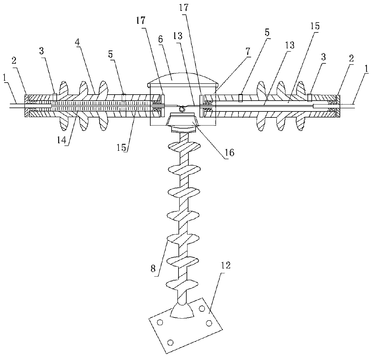
Figure 1 
Figure 2 
Figure 3
Abstract
Description
technical field
[0001] The invention relates to the technical field of electric special optical cables, in particular to a splicing device for high-voltage power grid phase-line composite optical cables (OPPC, Optical Phase Conductor) and a splicing method for high-voltage power grid phase-line composite optical cables. Background technique
[0002] Optical Phase Conductor OPPC (Optical Phase Conductor) is a new type of special optical cable for power. It is an optical cable that combines optical fiber units in the phase line. It has the dual functions of phase line and communication. It is mainly used for voltage levels below 110kV, urban and suburban distribution power grid, rural power grid.
[0003] In the medium and low voltage power grids, especially the distribution lines below 35kV, some ground wires may not be erected, so it is impossible to install OPGW (Optical Fiber Composite Overhead Grand Wire, overhead ground wire composite optical cable). In all power grids,...
Examples
Embodiment Construction
[0022] Such as figure 1 As shown, this splicing device for phase-line composite optical cables of a high-voltage power grid includes: an optical fiber channel insulating jacket 4, a disc fiber cavity 7, an insulating post 8, a base 12, a fiber core channel 15, and a splicing disc 16;
[0023] An insulating support 8 is arranged on the base 12, and a disk fiber chamber 7 is installed on the insulation pillar. The disk fiber chamber 7 has a chamber cover 6 and a fiber fusion disk 16 is placed therein, and the disk fiber chamber and the chamber cover are made of non-metallic insulating materials;
[0024] The fiber channel insulating jacket 4 sets outside the OPPC optical cable 1, the optical fiber 13 stripped from the OPPC optical cable 1 passes through the fiber core channel 15, enters from the left side of the fiber cavity 7 of the disk, and is fused through the fiber splicing tray 16. Right side output of chamber 7;
[0025] A glue injection hole 5 is provided on the left si...