
Chip-collecting device
A technology for recycling devices and swarf, which is applied in maintenance and safety accessories, electrode maintenance, electrode characteristics, etc., can solve problems such as increased load on the drive unit, device failure, etc., and achieves the effect of high swarf recycling capacity
Patent Information
- Authority / Receiving Office
- CN · China
- Patent Type
- Applications(China)
- Current Assignee / Owner
- Publication Date
- 2019-12-06
- Estimated Expiration
- Not applicable · inactive patent
Smart Images
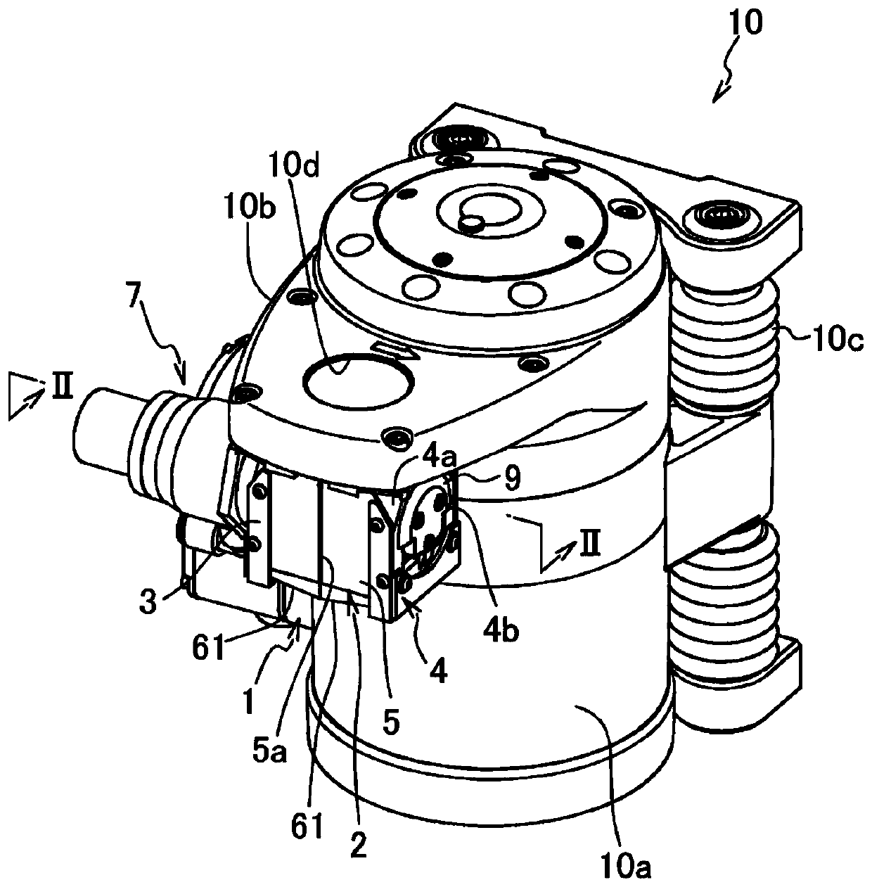
Figure 1 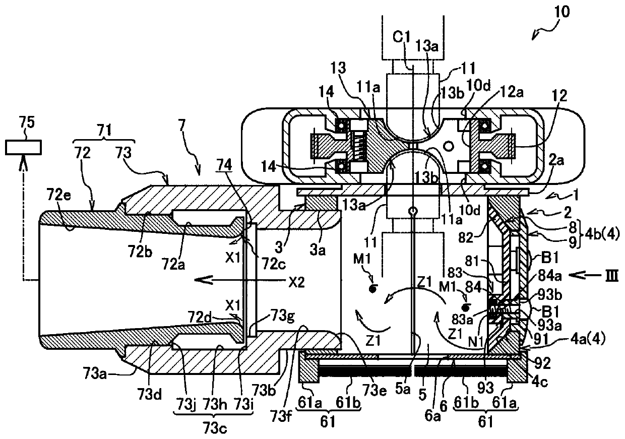
Figure 2 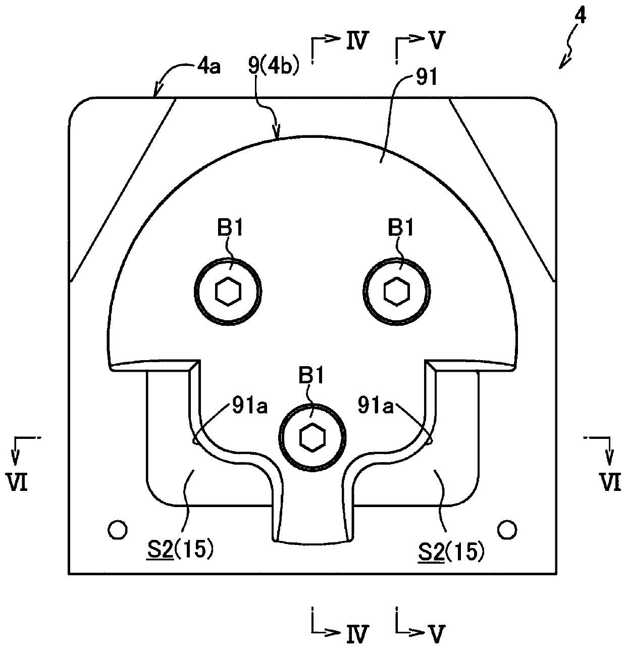
Figure 3
Abstract
Description
technical field
[0001] The present invention relates to a swarf recovery device for recovering swarf generated by the cutting operation when cutting the tip of a spot welding electrode tip with a tip dresser. Background technique
[0002] Conventionally, it is known that an oxide film adheres to the tip of an electrode tip during repeated welding operations in spot welding. Furthermore, if spot welding is performed directly with the oxide film adhering to the tip of the electrode tip, the quality of the welded part will deteriorate. Therefore, the tip of the electrode tip is usually cut regularly with a tip dresser to remove the oxide film.
[0003] However, if the chips generated when cutting the tip of the electrode tip with the tip dresser adhere to the driving part of the device, the load on the driving part will increase, and in the worst case, the device may break down. Chips are recovered immediately after they are generated.
[0004] In order to solve this problem,...
Examples
Embodiment Construction
[0033] Hereinafter, embodiments of the present invention will be described in detail with reference to the drawings. It should be noted that the following description of the preferred embodiments is exemplary only in nature.
[0034] figure 1 A tip dresser 10 to which the chip recovery device 1 according to the embodiment of the present invention is mounted is shown. Such as figure 2 As shown, the swarf recovery device 1 is used to recover swarf M1 generated when the tips 11 a of a pair of electrode tips 11 attached to a spot welding torch are respectively cut by the tip dresser 10 .
[0035] Such as figure 1 As shown, the above-mentioned electrode tip dresser 10 includes: a substantially cylindrical motor casing part 10a with the cylinder centerline direction facing the up and down direction; A plate-shaped gear case part 10b; and a shock absorbing mechanism part 10c attached to the back of the motor case part 10a to absorb the impact applied to the motor case part 10a. ...