

Multifunctional wool top pressing dust sticking mechanism
A multifunctional, wool-top technology, applied in textiles and papermaking, transportation and packaging, fiber processing, etc., can solve the problems of inconvenient wool surface looseness, inconvenient adjustment of wool top tension, poor dust removal effect, etc., to protect the vacuum cleaner and enrich practical functions , Concentrated cleaning effect
Patent Information
- Authority / Receiving Office
- CN · China
- Current Assignee / Owner
- Publication Date
- 2019-12-13
Smart Images
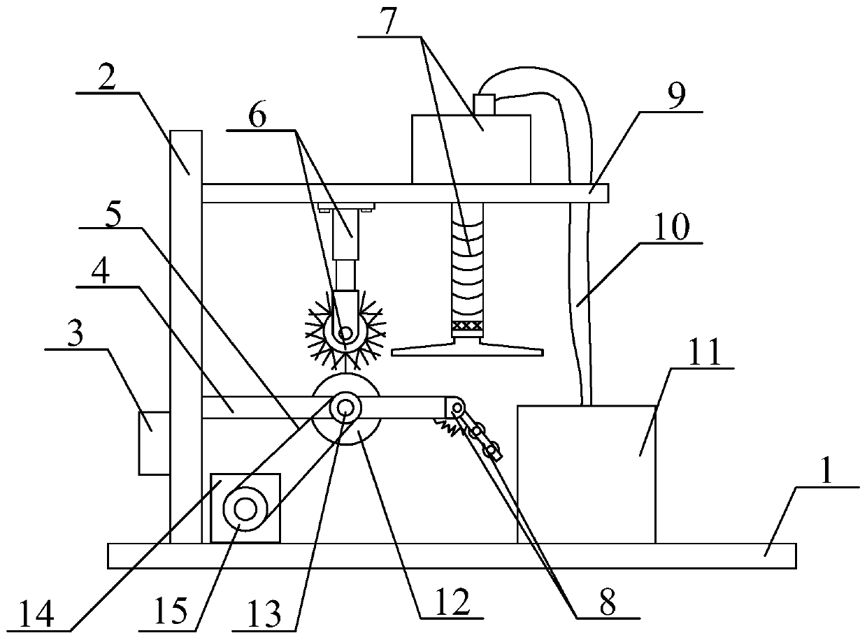
Figure 1 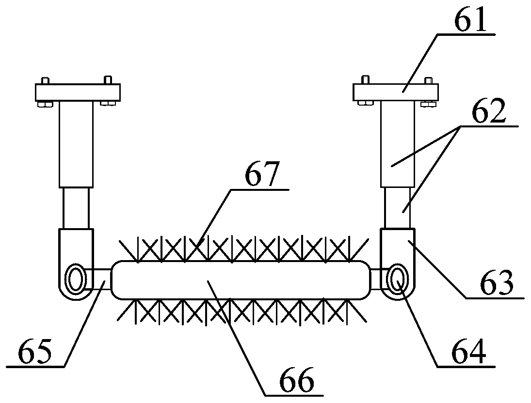
Figure 2 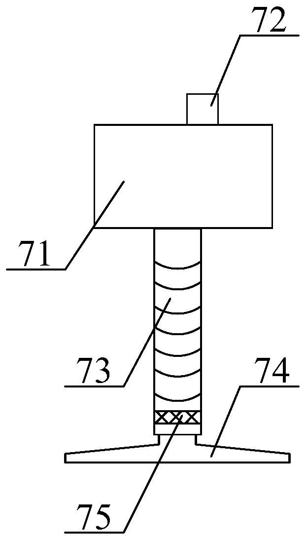
Figure 3
Abstract
Description
technical field
[0001] The invention belongs to the technical field of textile processing machinery and equipment, and in particular relates to a multifunctional wool top pressing and sticking dust mechanism. Background technique
[0002] Wool spinning is a spinning process that processes wool fibers into yarns. Wool spinning fibers are mainly wool, and also include special animal hairs such as cashmere, rabbit hair, mohair, yak hair, etc. The wool spinning process can also be used for wool-type chemical fiber pure spinning, Blended and blended with other natural fibers. Wool fabrics, knitted fabrics, blankets, etc. made of pure and blended wool yarns have the characteristics of warmth retention, moisture absorption, elasticity and wear resistance. Clothes made of wool fabrics feel soft, plump and scratchy. It can be used to weave industrial materials, stationery and carpets. The wool spinning system uses wool fiber and wool-type chemical fiber as raw materials, and the wh...
Examples
Embodiment Construction
[0034] The present invention will be further described below in conjunction with accompanying drawing:
[0035] as attached figure 1 To attach figure 2As shown, the present invention provides a multi-functional wool top pressing and sticking dust mechanism, including a support base plate 1, a support column 2, a control box 3, a lower horizontal strut 4, a drive belt 5, and a structure of a wool surface loosening roller with adjustable pressure 6. Filterable dander collection pipe structure 7, wool top tension adjustment frame structure 8, upper cross support rod 9, dust guide pipe 10, storage box 11, driving roller 12, driven wheel 13, driving motor 14 and driving wheel 15, The support column 2 is bolted to the left side of the upper surface of the support base plate 1; the control box 3 is bolted to the lower left side of the support column 2; the lower horizontal strut 4 is bolted to the support The lower position on the right side of the column 2; the drive belt 5 is sl...