
Air-breathing engine plasma ignition system
An ignition system and plasma technology, applied in the direction of machines/engines, gas turbine devices, mechanical equipment, etc., can solve the problems of unable to achieve multiple ignition of the engine, unable to meet the requirements of wide-area ignition of the engine, etc., to solve the problem of multiple starts and maneuvers The effect of flight flameout, strong energy designability, and expansion of working airspace
Patent Information
- Authority / Receiving Office
- CN · China
- Patent Type
- Applications(China)
- Current Assignee / Owner
- Publication Date
- 2020-03-17
- Estimated Expiration
- Not applicable · inactive patent
Smart Images
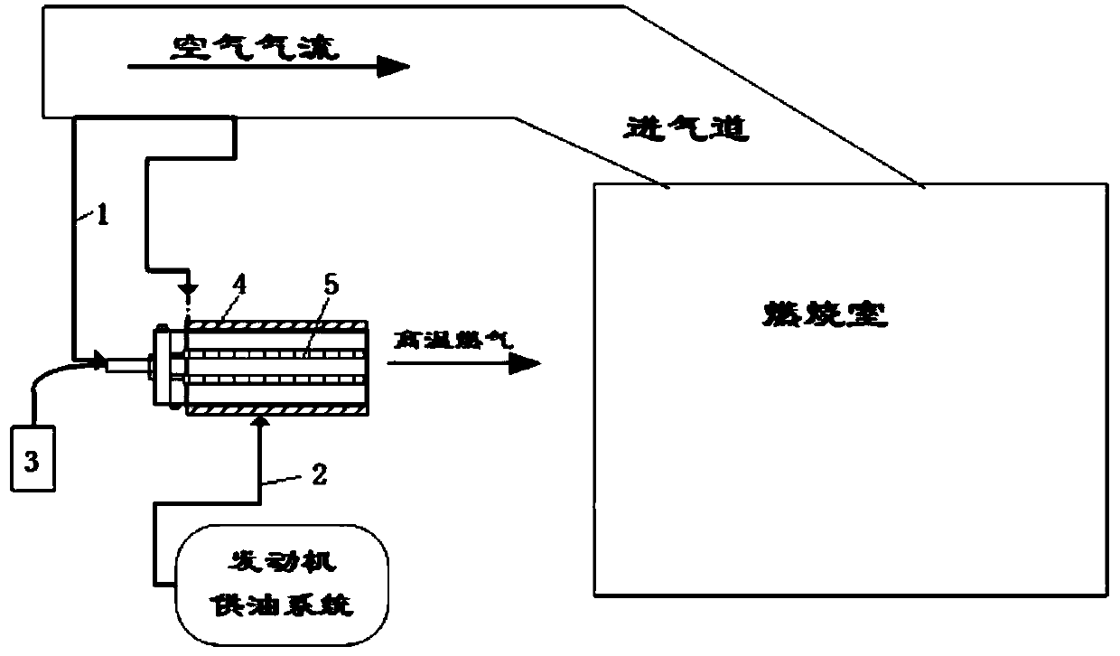
Figure 1 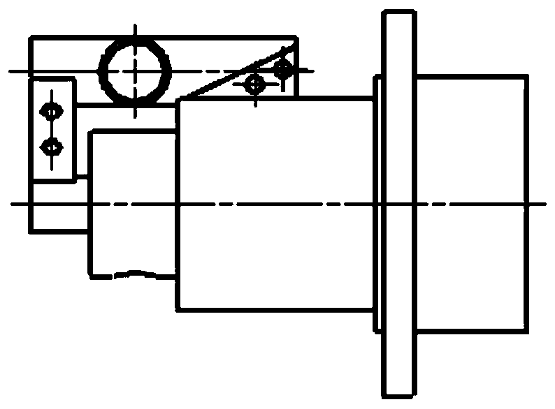
Figure 2 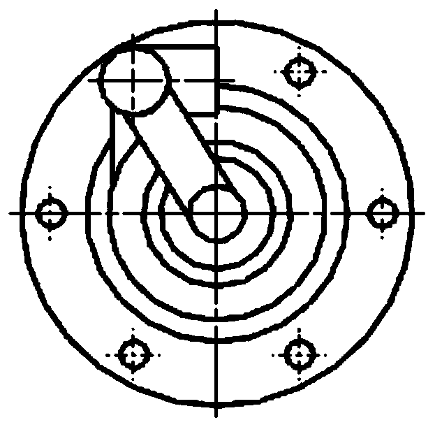
Figure 3
Abstract
Description
technical field
[0001] The invention belongs to the technical field of engine ignition, and in particular relates to an air-breathing engine plasma ignition system. Background technique
[0002] In order to meet the needs of wide-area, long-distance, and high-speed aircraft, the engine will be subject to instantaneous or continuous complex disturbances when it is changing stages, large maneuvering flight, or working conditions, which will easily cause the engine to stall. Therefore, the engine is required It has the ability of quick response, reliable and stable operation and multiple ignition in a large airspace.
[0003] At present, domestic and foreign air-breathing engines usually use pyrotechnic igniters and spark plug igniters as ignition devices. Among them, pyrotechnic igniters have good ignition performance and short ignition delay time, but they cannot achieve multiple ignitions of the engine, and spark plug ignition cannot meet the requirements. Engine wide area ...
Examples
Embodiment Construction
[0022] The present invention will be described in detail below with reference to the accompanying drawings and examples.
[0023] This embodiment provides an air-breathing engine plasma ignition system, see the attached figure 1 , including: bleed air pipeline 1, oil supply pipeline 2, power supply 3 and igniter housing;
[0024] One end opening of the igniter housing is used as an air outlet, and is connected with the air inlet of the combustion chamber of the engine. A high-voltage electrode 5, a low-voltage electrode 4 and an insulating ring are arranged in the igniter housing, and the high-voltage electrode 5 and the low-voltage electrode 4 are both Hollow cylinder, the low-voltage electrode 4 is coaxially installed outside the high-voltage electrode 5, an annular cavity is formed between the high-voltage electrode 5 and the low-voltage electrode 4, and an insulating ring is installed at one end of the annular cavity to realize the high-voltage electrode 5 and the low-volt...