
Network source coordination virtual synchronous machine control method of optical storage integrated system
A technology of virtual synchronous machines and control methods, applied in photovoltaic power generation, energy storage, climate change adaptation, etc., can solve problems such as limiting the promotion of VSG strategies, achieve the effects of reducing the range of variation, prolonging battery life, and ensuring system security
Patent Information
- Authority / Receiving Office
- CN · China
- Current Assignee / Owner
- Publication Date
- 2020-11-06
Smart Images
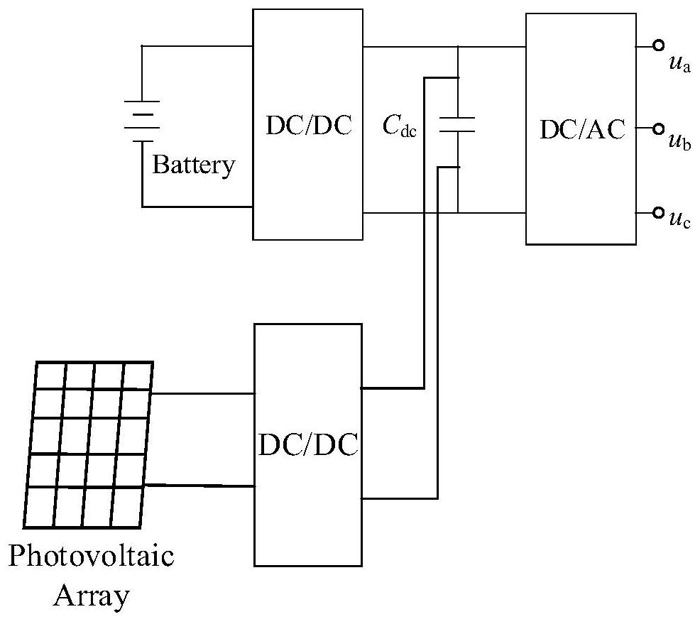
Figure 1 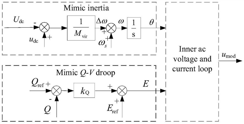
Figure 2 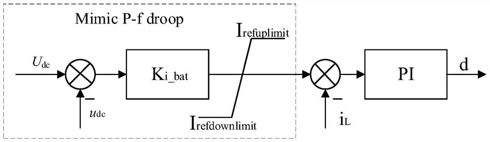
Figure 3
Abstract
Description
technical field
[0001] The invention belongs to the technical field of photovoltaics, energy storage and micro-grid control, and in particular relates to a method for controlling a network source coordination virtual synchronous machine of an integrated system of photovoltaics and storage. Background technique
[0002] In recent years, more and more new energy sources have been integrated into the grid through converters. Initially, new energy sources are connected to the grid with the maximum power output control strategy, so they do not respond to changes in grid-side power demand, which leads to a decrease in grid inertia and poor stability. Therefore, the new energy system is gradually required to have the ability of voltage regulation and frequency regulation and inertial support capability. Therefore, many strategies for controlling new energy grid-connected inverters to provide frequency and voltage support for the grid have been proposed. Among them, VSG has attract...
Examples
Embodiment
[0064] From two aspects of grid-side fluctuation and source-side photovoltaic output fluctuation, the superiority of the control strategy disclosed in the present invention over the control effect of traditional VSG is compared.
[0065] Both strategies are applied to figure 1 Same topology as shown, with same hardware parameters. In the initial state, the battery output current is 0A, and the photovoltaic output power of 1kW is sent to the grid through the inverter. At 0.6s, a sudden -8° phase disturbance on the grid side caused a sudden increase in the absorbed power on the grid side; at 1.2s, the photovoltaic output power began to ramp up (simulated illumination enhancement), and the photovoltaic power rose to 10kW within 0.1s.
[0066] When the traditional VSG control strategy is adopted, the response waveform of the integrated optical storage system is as follows: Figure 5 Shown in (a); when adopting the control scheme disclosed by the present invention, the response w...