
Side surface protection device for blocked pressure gauge
A protective device and type pressure gauge technology, which is applied in the direction of measurement, wellbore/well components, earthwork drilling and production, etc., can solve the problems of inability to disassemble twice, inconvenient maintenance of instruments, etc., achieve simple structure, convenient installation and use, and solve problems that cannot be solved The effect of individual maintenance
Patent Information
- Authority / Receiving Office
- CN · China
- Patent Type
- Applications(China)
- Current Assignee / Owner
- Publication Date
- 2020-12-01
- Estimated Expiration
- Not applicable · inactive patent
Smart Images
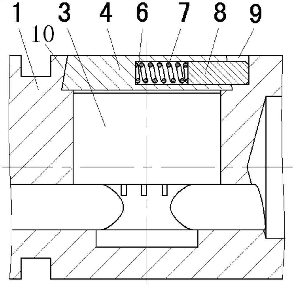
Figure 1 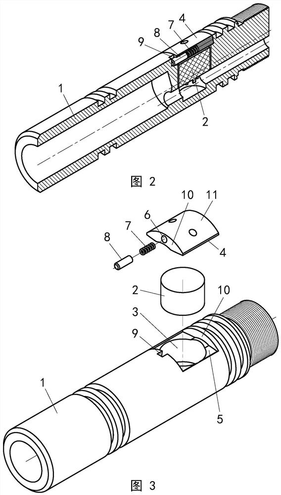
Figure 2
Abstract
Description
technical field
[0001] The invention relates to a side protection device for a plugging pressure gauge, which belongs to the technical field of downhole instrument structures. Background technique
[0002] The plugging pressure gauge is suitable for testing the formation pressure of the water injection well in the oil field. The instrument is installed in the water injection hole of the eccentric water distributor, and the formation pressure value is measured through the pressure sensor installed on the side. Due to the limitation of the structural space of the eccentric water distributor, the structural size of the blockage pressure gauge is very limited. Generally, the diameter of the instrument is not greater than 20mm, and the length is not greater than 200mm. Components such as sensors, circuit boards, and batteries must be installed in such a limited structural space, resulting in a very tight structural space for this type of instrument, and related structural design ...
Examples
Embodiment Construction
[0013] The present invention will be further described in detail below in conjunction with the accompanying drawings and embodiments.
[0014] A side protection device for a plugging pressure gauge of the present invention, such as Figure 1 ~ Figure 3 As shown, the device includes an instrument body 1; the instrument body 1 is provided with a circular cavity 3 for placing the pressure sensor 2, and the top of the circular cavity 3 is provided with a protective cover 4; the mouth of the circular cavity 3 is provided with a The cover plate groove 5 corresponding to the shape of the protective cover plate 4; one end of the protective cover plate 4 is provided with a blind hole 6, and a spring 7 and a limit pin 8 are arranged in the blind hole 6; Limit pin groove 9. Between the two ends of the instrument body 1 and the protective cover 4 is an embedded fitting structure of a slope 10 . The top surface of the protective cover plate 4 is an arc surface 11 with the same radius as ...