
Functional exercise device for critical patient
An exercise device and patient technology, applied in passive exercise equipment, physical therapy and other directions, can solve problems such as lower limb exercise for critically ill patients
Patent Information
- Authority / Receiving Office
- CN · China
- Patent Type
- Applications(China)
- Current Assignee / Owner
- Publication Date
- 2021-07-06
Smart Images
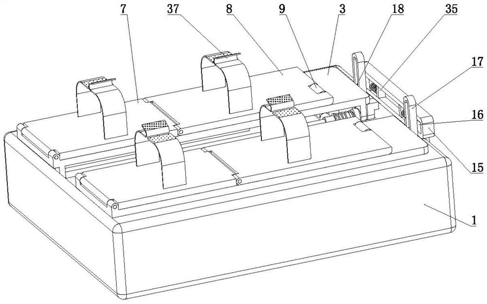
Figure 1 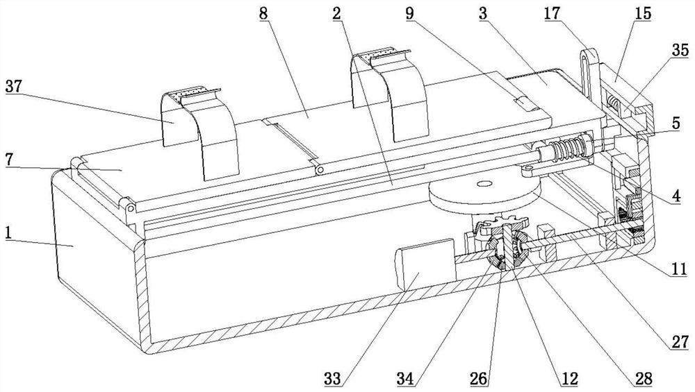
Figure 2 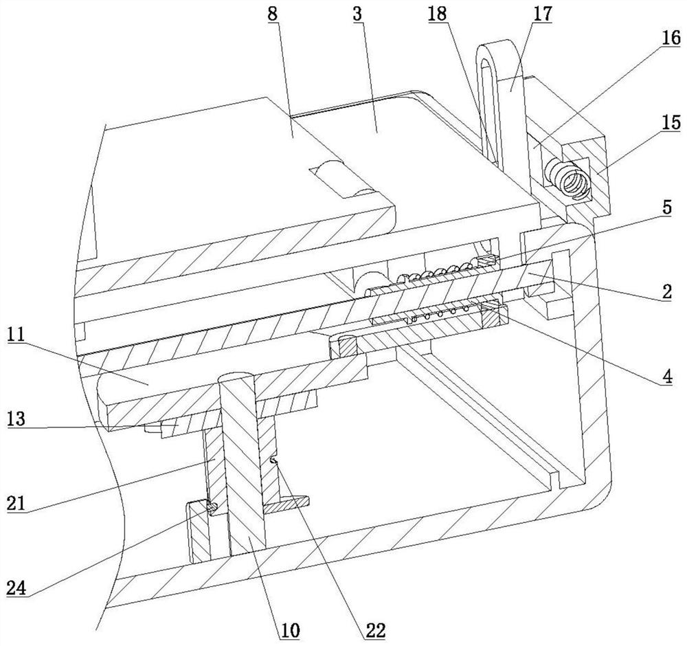
Figure 3
Abstract
Description
technical field
[0001] The invention relates to the technical field of critical care equipment, in particular to a functional exercise device for critically ill patients. Background technique
[0002] Severely ill patients are often in serious condition, often accompanied by multi-organ (lung, kidney, liver, etc.) failure or in a coma, unable to take care of themselves, and completely bedridden. Severely ill patients who stay in bed for a long time can easily lead to muscle weakness and limb movement barriers. If the patient cannot perform joint activities in the optimal activity period in time, resulting in joint stiffness, muscle atrophy and other adverse consequences, it will seriously affect the patient's health. Mobility after recovery.
[0003] When performing rehabilitation exercises on the lower limbs of critically ill patients, it is necessary to use some auxiliary exercise equipment, but these equipment can only exercise a single joint of the patient's lower limbs...
Examples
Embodiment Construction
[0016] The specific implementation manners of the present invention will be described in further detail below in conjunction with the accompanying drawings.
[0017] Depend on Figure 1 to Figure 8 Given, including a box body 1 with an upper end opening, the front and rear sides of the box body 1 are respectively hinged with a support plate 3 through left and right axial pin shafts 2, and the right side of the pin shaft 2 is slidingly connected to a cylinder 4, and the right side of the cylinder 4 is connected to the cylinder 4 through The compression spring is slidably connected with a circular ring 5, the right side of the support plate 3 is provided with a left and right through groove 6, the left end of the support plate 3 is hinged with a first supporting plate 7, and the right end of the first supporting plate 7 is hinged with a first supporting plate located above the through groove 6. Two supporting plates 8, the left end of the cylinder 4 is provided with a connecting...