
A real-time cable force identification method based on improved s-transform
An identification method and cable force technology, applied in the field of real-time cable force identification based on improved S-transform, can solve the problems of time positioning failure at low frequencies, too narrow, frequency positioning failure at high frequencies, etc., to improve energy aggregation and time The effect of frequency resolution
Patent Information
- Authority / Receiving Office
- CN · China
- Patent Type
- Patents(China)
- Current Assignee / Owner
- Publication Date
- 2022-06-21
Smart Images
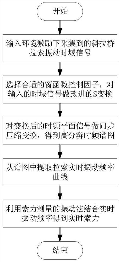
Figure 1 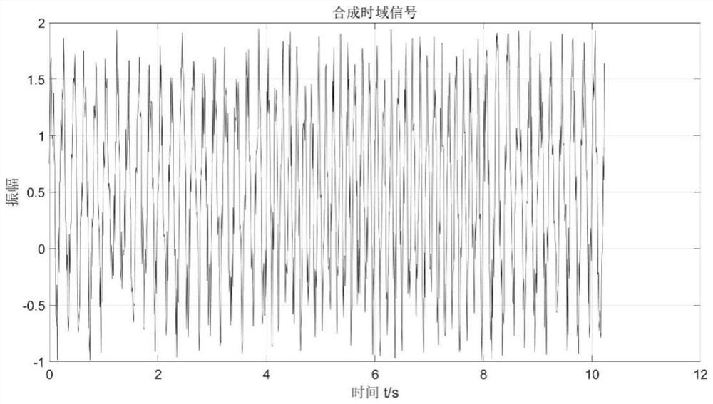
Figure 2 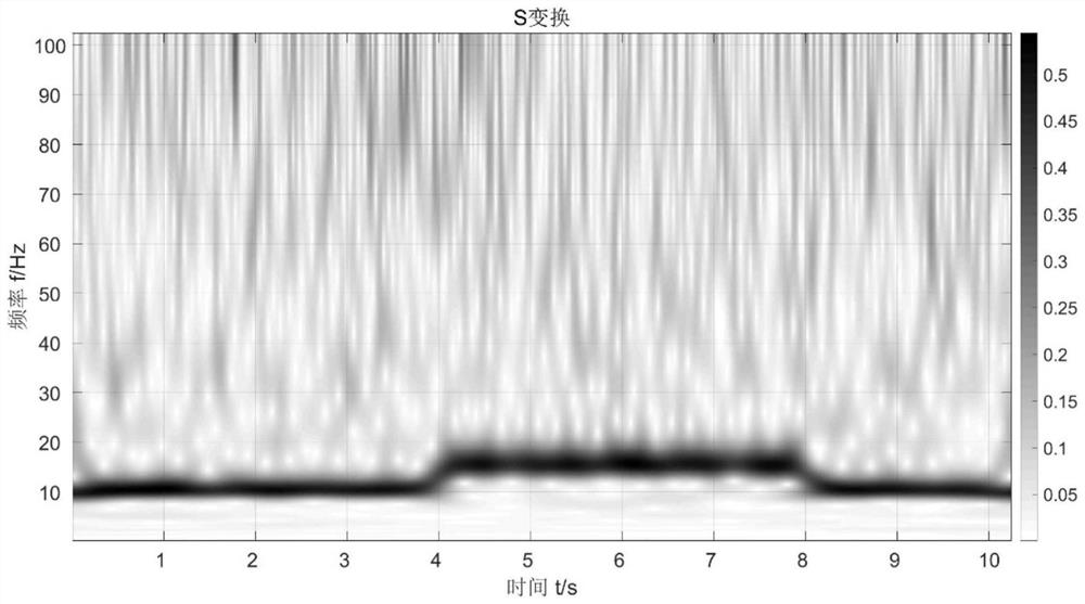
Figure 3
Abstract
Description
technical field
[0001] The invention relates to the field of bridge structure health monitoring, in particular to a real-time cable force identification method based on improved S transform. Background technique
[0002] As an important national infrastructure, bridges are an important part of transportation routes. Cable-stayed bridges are widely used in bridge construction due to their advantages of good mechanical performance, large span and beautiful appearance. The stay cable is one of the main stress components of the cable-stayed bridge. The health monitoring of the stay cable, especially the identification and estimation of the cable force, is very important for the maintenance and safety assessment of the cable-stayed bridge.
[0003] At present, the cable force measurement methods of cable-stayed bridges mainly include: oil pressure gauge reading method, pressure sensor method, magnetic flux method, vibration method, etc. Among them, the vibration method is easy ...
Examples
Embodiment 1
[0082] The present invention will be further described in detail below with reference to specific embodiments and accompanying drawings.
Embodiment
[0084] Taking the simulated synthetic signal as an example, the sampling frequency is 100Hz, and the number of sampling points is N=1024. The analytical formula is:
[0085]
[0086] According to the processing method of the present invention, the simulated synthetic signal is input on the MATLAB software platform, such as figure 2 As shown, the time-domain signal of the cable-stayed bridge cable vibration collected under the excitation of the simulated environment. First, do S-transform on the signal, and the obtained time-spectrogram is as follows image 3 shown; then take γ GST = 0.1, Increase the front taper of the window function, and the obtained time-spectrogram is as follows Figure 4 show; will and After replacing the position of , the back taper of the window function can be increased accordingly, and the obtained time-spectrogram is as follows Figure 5 shown. Will Figure 4 and Figure 5 and image 3 It can be seen from the comparison that the impr...