
Single-pole double-throw coplanar waveguide type radio frequency mechanical switch structure
A coplanar waveguide, single-pole double-throw technology, applied in the direction of waveguide-type devices, electrical components, circuits, etc., can solve the problem of miniaturization, integration indicators cannot form a qualitative breakthrough, and the size of the switch body cannot be miniaturized and improved. requirements and other issues, to achieve the effects of miniaturization, size reduction, and low insertion loss
Patent Information
- Authority / Receiving Office
- CN · China
- Patent Type
- Applications(China)
- Current Assignee / Owner
- Publication Date
- 2021-09-03
Smart Images
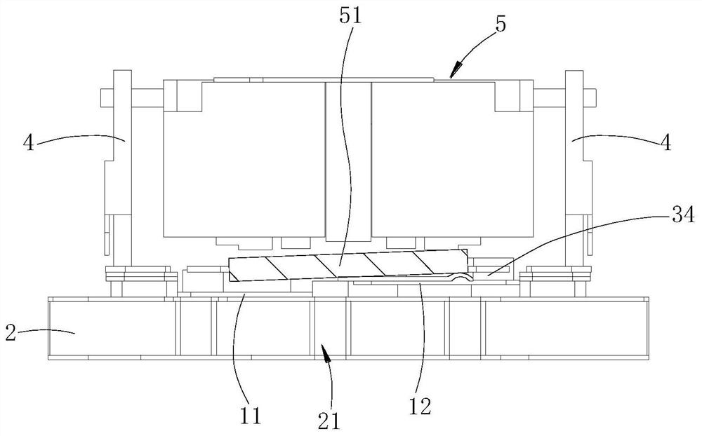
Figure 1 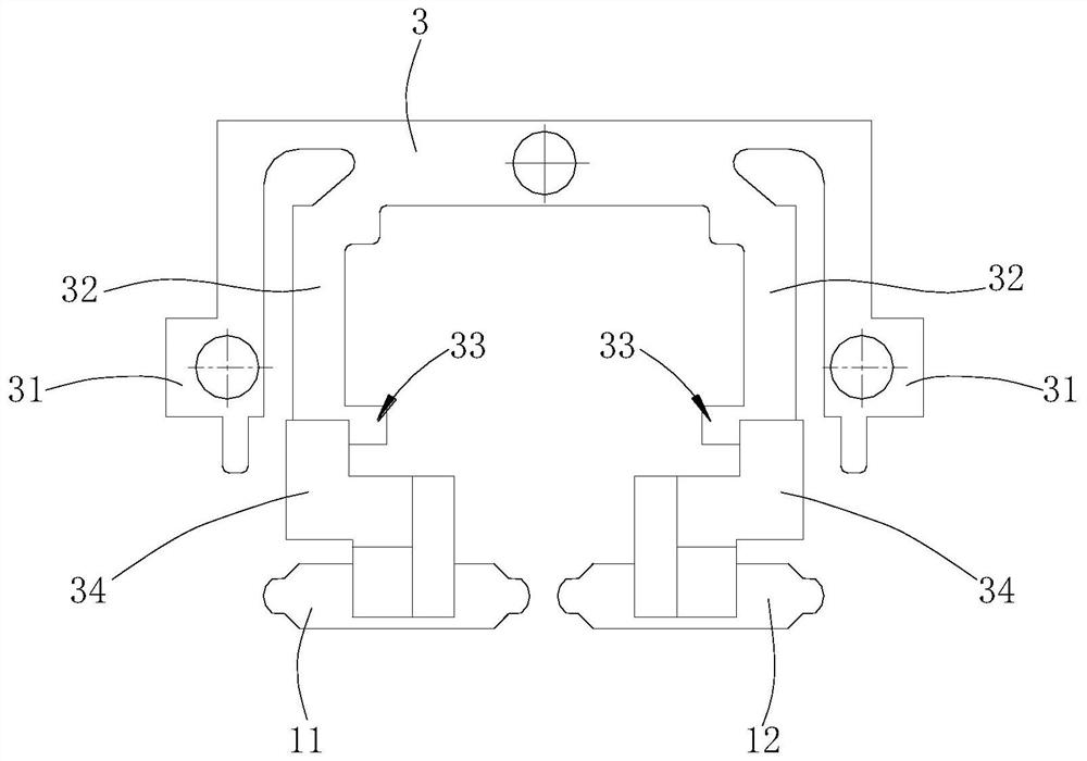
Figure 2 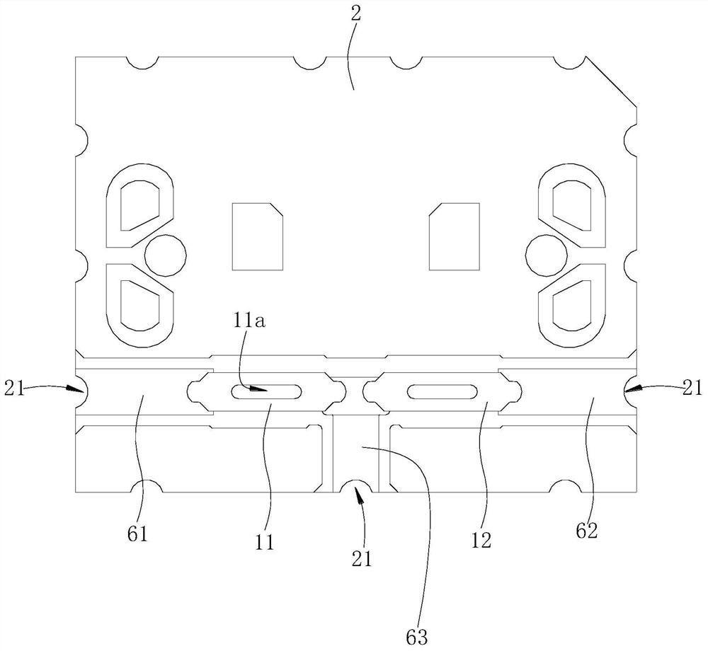
Figure 3
Abstract
Description
technical field
[0001] The invention relates to a single pole double throw coplanar waveguide type radio frequency mechanical switch structure. Background technique
[0002] The radio frequency mechanical switch is mainly composed of three parts: signal control system, electromagnetic conversion system and microwave transmission system. The microwave transmission system is the actuator to realize microwave signal transmission / switching, and is the core of the radio frequency mechanical switch. An excellent microwave transmission system is the key to realize the high performance of the relay. The microwave transmission system of the traditional switch is composed of a rectangular transmission line microwave cavity and a circular coaxial transmission line connector assembly. The external dimensions of this type of radio frequency mechanical switch greatly restrict the development of products.
[0003] The miniaturization design of the RF mechanical switch structure has been ...
Examples
Embodiment Construction
[0025] Such as Figures 1 to 3 shown.
[0026] The switch structure includes a radio frequency substrate 2, a transmission reed 3, two radio frequency reeds and three microstrip pieces.
[0027] The two RF reeds are hard gold plated on the surface of beryllium copper material, the two RF reeds are respectively the first RF reed 11, the second RF reed 12, the structure of the first RF reed 11 and the second RF reed 12 Similarly, taking the first radio frequency reed 11 as an example, the first radio frequency reed 11 includes a horizontal plate body and a vertical portion, the upper end of the horizontal plate body has an assembly groove 11a, and the assembly groove 11a extends into the vertical portion.
[0028] The RF substrate 2 adopts Rogers 4003 board, which is coated with copper on both sides and then gold-plated. Three microstrips are respectively welded on the RF substrate 2. The three microstrips are independent of each other. The three microstrips are J1 microstrips ...