
A welding equipment for large gas regulating valve
A technology for gas adjustment and welding equipment, applied in welding equipment, welding equipment, auxiliary welding equipment, etc., can solve the problems of inability to locate the flange, large flange volume, inconvenient flange adjustment, etc., to achieve continuous welding operation and reduce processing. Difficulty, the effect of reducing production costs
Patent Information
- Authority / Receiving Office
- CN · China
- Patent Type
- Patents(China)
- Current Assignee / Owner
- Publication Date
- 2022-07-01
Smart Images
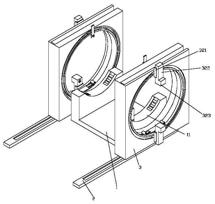
Figure 1 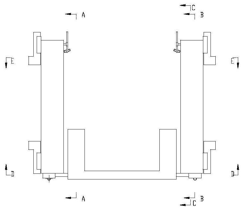
Figure 2 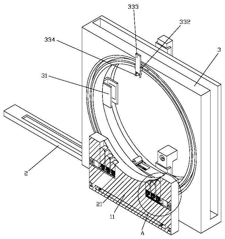
Figure 3
Abstract
Description
technical field
[0001] The invention belongs to the technical field of valve body processing, and in particular relates to a welding device for a large gas regulating valve. Background technique
[0002] The gas pressure regulator is commonly known as the pressure reducing valve, also known as the gas pressure regulating valve, which is a device that automatically changes the gas flow through the regulating valve to keep the outlet gas at the specified pressure. It is usually divided into two types: direct-acting and indirect-acting.
[0003] Large gas control valves need to weld flanges on both ends of the valve body during processing. The flanges need to be positioned on the flange holes during welding to ensure that the flanges are welded on the valve body at the specified position. Due to the huge valve body, The corresponding flange volume is also large, which is very inconvenient to adjust with the flange, and at the same time it is impossible to position the flange. ...
Examples
Embodiment Construction
[0044] like Figure 1-28 As shown in the figure, a welding equipment for a large gas regulating valve includes a base plate 1, a support base 11 arranged on the base plate 1, and a material carrier frame 3 arranged on both sides of the base plate 1. There is a first material loading slot, a first movable slot is arranged on the side wall of the upper side of the loading frame 3, and two sets of first movable blocks 32 are arranged in the first movable slot. 32 is provided with a first connecting block 323, the first connecting block 323 is provided with a second movable groove, the second movable groove is provided with a first connecting rod 324, and one end of the first connecting rod 324 is provided with A first connecting spring 3241, the first connecting block 323 is provided with a motor 327 for driving the first connecting rod 324 to move in the second movable groove; A sixteenth movable slot is provided, a movable ring 33 is arranged in the sixteenth movable slot, and...