
Node withdrawing device and node withdrawing method for vertical traction rod
A drawbar, vertical technology, applied in the field of retreating node devices, can solve problems such as damage, irregular operation, no vertical setting, etc.
Patent Information
- Authority / Receiving Office
- CN · China
- Patent Type
- Applications(China)
- Current Assignee / Owner
- Publication Date
- 2022-01-28
Smart Images
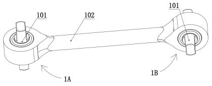
Figure 1 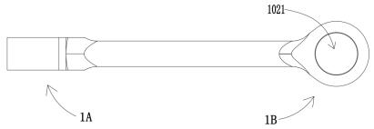
Figure 2 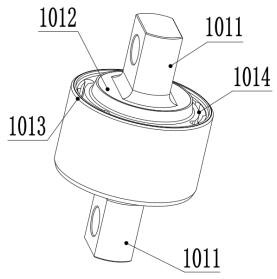
Figure 3
Abstract
Description
technical field
[0001] The invention relates to a node withdrawal device for a vertical draw rod, which belongs to the technical field of processing equipment for a vertical draw rod, and is used for withdrawing a rubber node in a vertical draw rod from a rod body of the vertical draw rod. The invention also relates to a method for withdrawing the node of the vertical drawbar. Background technique
[0002] Vertical drawbars are usually used in the bogie structure of rail vehicles, mainly for connection and shock absorption. Such as Figure 1-Figure 3 As shown, in the metal inner hole 1021 of the vertical drawbar body, a rubber node 101 is usually press-fitted to buffer the rail vehicle and improve the running stability of the vehicle body and the comfort of the passengers. Such as figure 1 As shown, there is a vertical traction rod, including a transverse traction end 1A and a longitudinal traction end 1B, the mandrel of the rubber node 101 press-fitted in the transverse ...
Examples
Embodiment Construction
[0043] The following is attached Figure 1-10 The present invention is further described in detail.
[0044] Retraction devices for vertical drawbars, such as Figure 1-3 As shown, the vertical traction rod 1 includes a rod body and a rubber node 101. Both sides of the rod body include two inner holes 1021, and the two inner holes 1021 are equipped with rubber nodes 101. The rubber node 101 includes an outer casing 1013 and is located on the outer casing The mandrel in 1013, the rubber body 1014 is vulcanized between the jacket 1013 and the mandrel, the mandrel includes two flat squares 1011 of the mandrel, and the part of the mandrel between the two flat squares 1011 is the axis 1012 of the mandrel ;Such as figure 1 As shown, the core axes of the two rubber nodes 101 of the vertical traction rod 1 in this solution are perpendicular to each other, and the vertical traction rod 1 includes a longitudinal connection end 1A and a transverse connection end 1B.
[0045] The node...