
Fuel cell system, fuel cell vehicle, and method for controlling fuel cell system
a fuel cell and system technology, applied in the direction of battery/fuel cell control arrangement, battery/cell propulsion, battery/cell control arrangement, etc., can solve the problems of power drop to 0, slow response of air compressor, and low fuel efficiency of secondary batteries,
Patent Information
- Authority / Receiving Office
- US · United States
- Patent Type
- Patents(United States)
- Current Assignee / Owner
- Publication Date
- 2018-10-30
Smart Images
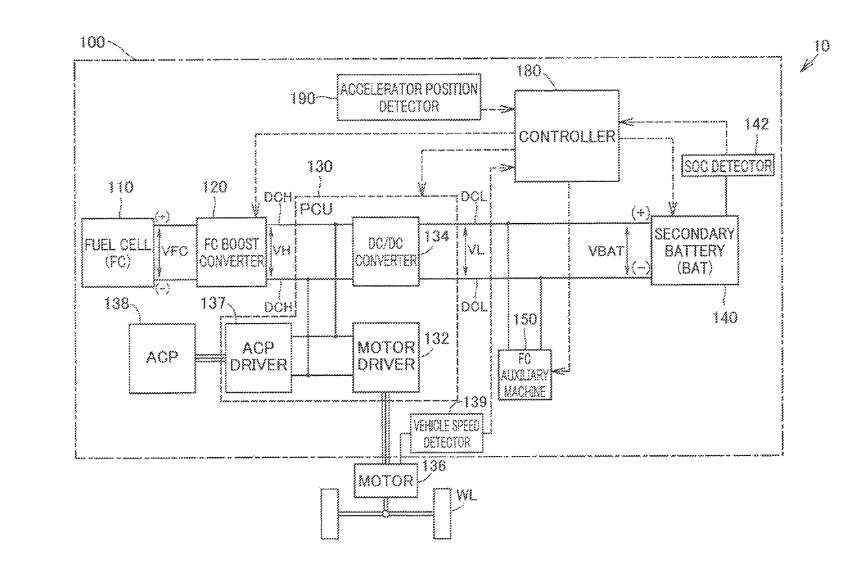
Figure 1 
Figure 2 
Figure 3
Abstract
Description
CROSS-REFERENCE TO RELATED APPLICATION
[0001] This application claims priority to Japanese Patent Application No. 2014-231342 filed on Nov. 14, 2014, the entire contents of which are incorporated herein by reference.BACKGROUND
[0002] Field
[0003] The present invention relates to a fuel cell system installed in a vehicle, a fuel cell vehicle, and a method for controlling the same.
[0004] Related Art
[0005] In some conventionally known fuel cell systems installed in a vehicle, required generated power of a fuel cell is calculated in accordance with an accelerator depression amount, and amounts of oxygen and hydrogen supplied to the fuel cell are controlled in such a manner that the power generated by the fuel cell matches the required generated power (JP-A-2011-15580). In the fuel cell system, when the required generated power of the fuel cell drops due to the deceleration of the vehicle or the like, required driving power of an air compressor that supplies oxygen to the fuel cell drops.
[0006] H...
Examples
first embodiment
A. First Embodiment
[0021]FIG. 1 is a schematic view illustrating a configuration of a fuel cell vehicle 10 including a fuel cell system 100 according to a first embodiment. The fuel cell vehicle 10 includes a fuel cell 110, an FC boost converter 120, a power control unit (PCU) 130, a traction motor 136, an air compressor (ACP) 138, a vehicle speed detector 139, a secondary battery 140, an SOC detector 142, FC auxiliary machine 150, a controller 180, an accelerator position detector 190, and wheels WL. The fuel cell vehicle 10 travels by driving the traction motor 136 by power supplied from the fuel cell 110 and from the secondary battery 140. For example, the fuel cell system 100 includes the functional units of the fuel cell vehicle 10 described above, except for the traction motor 136 and the wheels WL.
[0022]The fuel cell 110 is a polymer electrolyte fuel cell that generates power by receiving oxygen and hydrogen as reaction gas. The fuel cell 110 is not limited to the polymer ele...
second embodiment
B. Second Embodiment
[0050]FIG. 6 is a timing chart exemplarily illustrating a state of a fuel cell vehicle 10A according to a second embodiment. FIG. 6 exemplarily illustrates how the accelerator depression amount DACC, the vehicle speed SVHCL, the allowable output upper limit Wout of the output power Pout of the secondary battery 140, and an ON / OFF state of a required driving power lower limit setting control execution flag change over time. The fuel cell vehicle 10A according to the second embodiment is the same as the fuel cell vehicle 10 according to the first embodiment, except for the content of the “preset condition” in step S110 in the required driving power lower limit setting control (FIG. 3). The “preset condition” for the fuel cell vehicle 10A according to the second embodiment is the drop rate |ΔDACC|(0>ΔDACC) of the accelerator depression amount DACC per unit time being equal to or higher than a threshold ΔDth2 (for example, 5 [% / s]), the vehicle speed SVHCL of the fue...
third embodiment
C. Third Embodiment
[0052]FIG. 7 is a schematic view exemplarily illustrating a relationship between the allowable output upper limit Wout of the output power Pout of the secondary battery 140 and the lower limit PLRQ of the ACP required driving power PRQ, according to a third embodiment. The fuel cell vehicle 10B according to the third embodiment is the same as the fuel cell vehicle 10 according to the first embodiment except for how the lower limit PLRQ is set. The lower limit PLRQ according to the third embodiment is a variable value corresponding to values of the allowable output upper limit Wout and the vehicle required power PVHCL. The allowable output upper limit Wout according to the third embodiment is the smaller one of the allowable output upper limit Wout, obtained from the SOC charge-discharge characteristic, and the allowable output upper limit Wout, obtained from the temperature charge-discharge characteristic, as in the first embodiment. The PM-ECU 181 according to th...