
Prognostic system and method for an electric coolant pump
a technology of electric coolant and diagnostic system, which is applied in the direction of engine cooling apparatus, positive displacement liquid engine, failure safe, etc., can solve the problems of low coolant flow rate, coolant leakage, overheating of the engine or connected system components, etc., and achieve the effect of facilitating the estimation of a numeric state of health
Patent Information
- Authority / Receiving Office
- US · United States
- Patent Type
- Patents(United States)
- Current Assignee / Owner
- Publication Date
- 2019-04-30
Smart Images
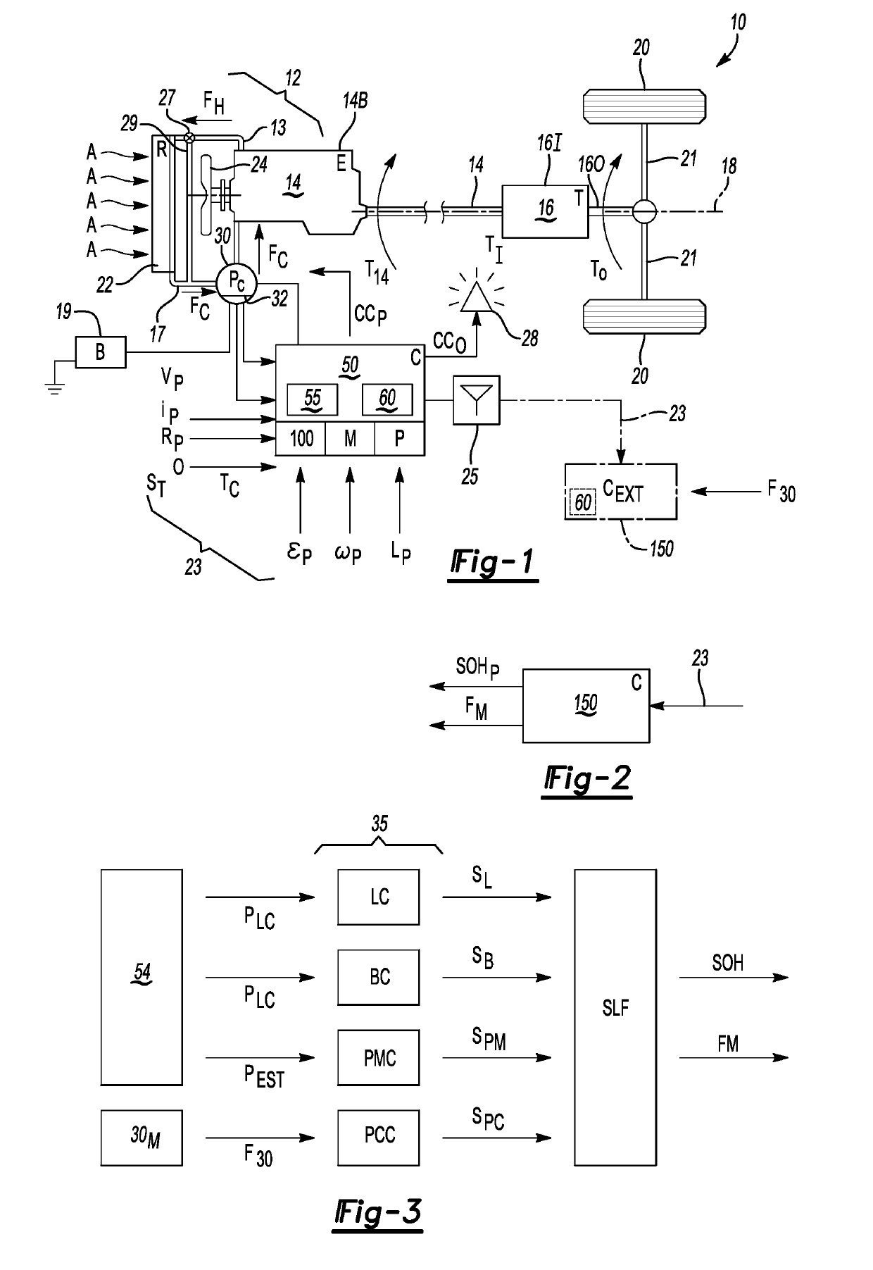
Figure 1 
Figure 2
Abstract
Description
INTRODUCTION
[0001] Vehicles and other systems may employ an internal combustion engine as a torque-generating device. As internal combustion engines generate intense heat during operation, thermal management techniques are used to maintain engine temperature within a desired temperature range. Cooling of the engine and connected components may be achieved by circulating water, antifreeze, or another suitable coolant to a cylinder head and engine block of the engine where engine heat is extracted. The heated coolant is then fed into and cooled by a radiator assisted by ambient air and a cooling fan before re-entering the engine.
[0002] Coolant pumps, colloquially known as water pumps, are the particular pumping devices used to circulate coolant in a closed fluid conduit loop. Inside the pump, rotating impeller blades move the coolant through the pump body and out to the engine. Mechanical coolant pumps are typically driven at engine speed by a rotating belt and engine-driven pulleys. Al...
Examples
Embodiment Construction
[0018]Referring to the drawings, wherein like reference numbers refer to like components, FIG. 1 provides a schematic view illustration of a vehicle 10 having a thermal management system 12 that is operable for regulating a temperature of a heat source, shown as an example internal combustion engine (E) 14 having an engine block 14B. In operation, the engine 14 provides engine torque (arrow T14) to a transmission (T) 16 arranged on a driveline 18 along with the engine 14, with the engine 14 and transmission 16 coupled to each other via a hydrodynamic torque converter or an input clutch (not shown). An input member 161 of the transmission 16 is thus supplied with an input torque (arrow TI) that may be selectively assisted as needed by an electric motor (not shown) in optional hybrid embodiments. Within the transmission 16, one or more gear sets and additional clutches (not shown) transfer the input torque (arrow TI) to an output member 160 to thereby deliver an output torque (arrow T...