
Voltage converter without electrolytic capacitor
a voltage converter and capacitor technology, applied in the direction of electric variable regulation, process and machine control, instruments, etc., can solve the problems of reducing safety, affecting electrical devices, and lowering span life, so as to improve service life, easy to carry without electrolytic capacitors, and output voltage
Patent Information
- Authority / Receiving Office
- US · United States
- Patent Type
- Patents(United States)
- Current Assignee / Owner
- Publication Date
- 2019-05-14
Smart Images
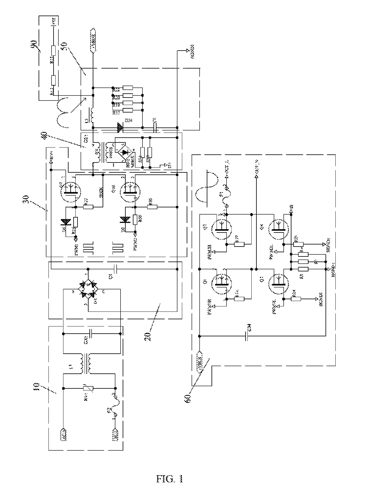
Figure 1 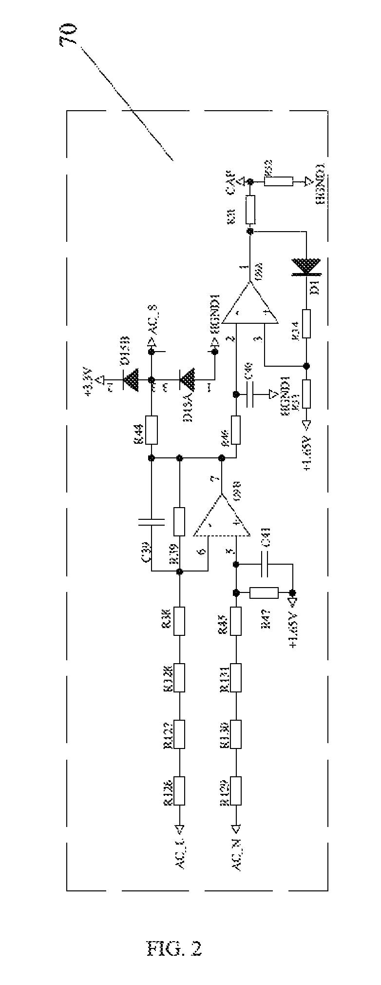
Figure 2 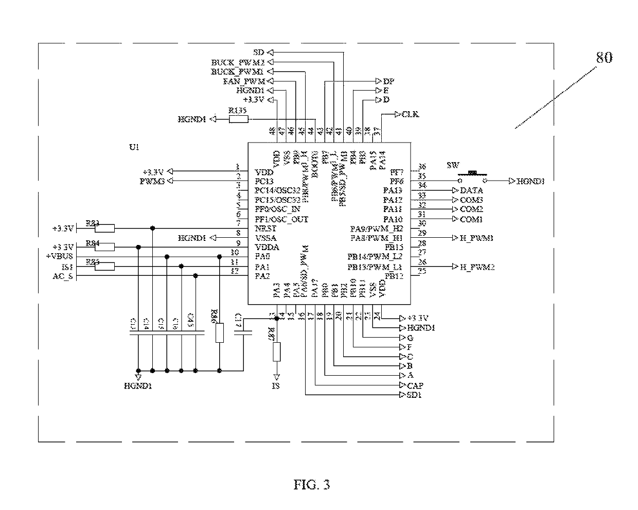
Figure 3
Abstract
Description
BACKGROUND1. Technical Field
[0001] The present disclosure generally relates to voltage converters field, and especially relates to a long-life intelligent step-down conversion device without electrolytic capacitors.2. Description of Related Art
[0002] The sine wave step-down conversion device, also known as a step-down travel platooninsert, is a sine wave AC / AC converter, which the function of step-down and stable voltage and frequency can be realized in the AC / AC transformation process. At present, most AC / AC portable devices in the market output modified waves, the voltage is firstly rectified to a DC voltage by a step-down circuit, secondly filtered by an aluminum electrolytic capacitor, thirdly stepped down by the BUCK and finally inverted. However, the kind of voltage output from the step-down conversion device is mostly modified wave, which is quite harmful to electrical devices. Meanwhile, most of it is filtered with aluminum electrolytic capacitors, which seriously results in l...
Examples
Embodiment Construction
[0020]The disclosure is illustrated by way of example and not by way of limitation in the figures of the accompanying drawings, in which like reference numerals indicate similar elements.
[0021]Referring to FIGS. 1-3, a long-life intelligent step-down conversion device in accordance with an exemplary embodiment of the present disclosure includes a high-frequency modulation unit 30, an inductance filtering unit 50 and an inverting paraphase unit 60.
[0022]The high-frequency modulation unit 30 includes a first switching tube Q7 and a second switching tube Q10, the drain of the first switching tube Q7 is connected to a DC voltage, the source of the first switching tube Q7 is connected to the drain of the second switching tube Q10, and the source of the second switching tube Q10 is earthed. The grids of the first and second switching tubes Q7, Q10 are respectively connected to two-path anti-phased PWM pulse signals.
[0023]The inductance filtering unit 50 includes a filtering inductor L3. T...