
Turbine blade cooling
a turbine blade and cooling technology, applied in the direction of blade accessories, engine fuctions, machines/engines, etc., can solve the problems of reducing the efficiency of the turbine assembly, reducing efficiency, and reducing the total loss of the turbine assembly by 30% or more, so as to achieve greater cooling, more film cooling channels, and greater flexibility in the arrangement of film cooling channels
Patent Information
- Authority / Receiving Office
- US · United States
- Patent Type
- Patents(United States)
- Current Assignee / Owner
- Publication Date
- 2020-11-03
Smart Images
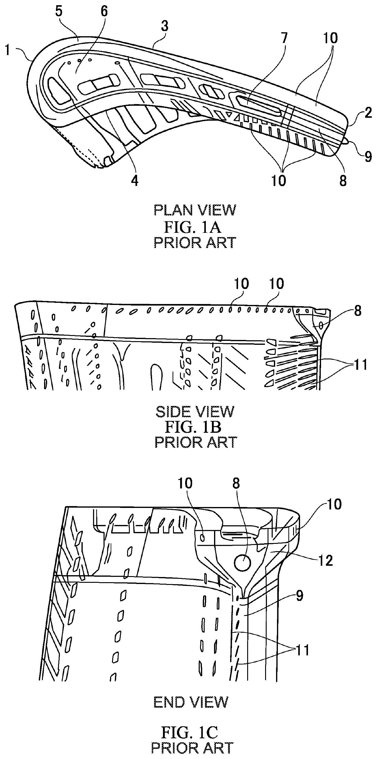
Figure 1 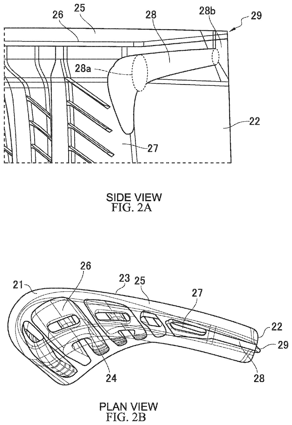
Figure 2 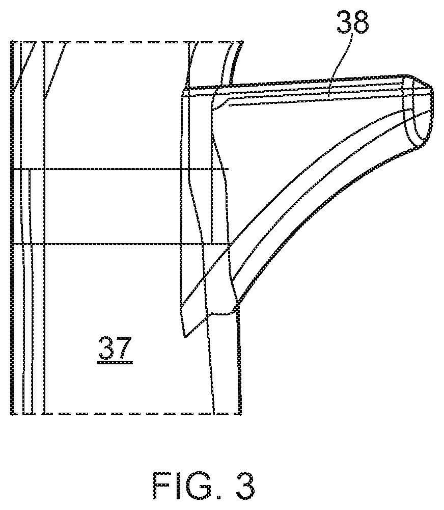
Figure 3
Abstract
Description
FIELD OF INVENTION
[0001] The present invention relates to shroudless turbine blades. More particularly the invention relates to the arrangement of internal cooling channels in the tip region of such blades and the geometry of the blades at their tip.BACKGROUND TO INVENTION
[0002] In a gas turbine engine, a compressor is arranged to compress air for delivery to a combustor. The combustor mixes the compressed air with fuel and ignites the mixture. Gas products of this combustion are directed at a turbine blade assembly causing rotation of the blades and the production of power from the turbine assembly. Combustion temperatures may exceed 1400° C. and typical configurations expose the turbine blade assemblies to these high temperatures. Turbine blades are made of materials capable of withstanding such high temperatures and often contain cooling systems for prolonging the life of the blades, reducing the likelihood of failure as a result of exposure to these excessive temperatures.
[0003] A ...
Examples
Embodiment Construction
[0031]FIG. 2 shows side and plan views of a blade tip configured in accordance with the invention. As can be seen, the tip includes a leading edge 21, a trailing edge 22, a suction side 23, a pressure side 24, and a squealer wall 25 extending around the perimeter of the tip. The squealer wall 25 bounds a gutter 26. Extending through the elongated portion of the blade in a root to tip direction is a main trailing edge cooling channel 27. The main trailing edge cooling channel 27 exits into the gutter 26. The main trailing edge cooling channel 27 is integrally cast into the blade, its shape being defined by a core positioned in a mould during casting of the blade. The core is subsequently leached out of the cast blade leaving the internal channel 27. As compared to the prior art, the core for manufacturing the illustrated embodiment is extended to include a gallery channel section which defines the gallery channel 28. The gallery channel has an open end 28a intersecting the main trail...