
Spark plug
a plug and spark technology, applied in the field of spark plugs, can solve the problems of easy side discharge, adversely affecting ignitability, and poor wear resistance of the discharge portion, and achieve the effect of excellent ignitability and small siz
Patent Information
- Authority / Receiving Office
- US · United States
- Patent Type
- Applications(United States)
- Current Assignee / Owner
- Publication Date
- 2005-03-17
- Estimated Expiration
- Not applicable · inactive patent
Smart Images
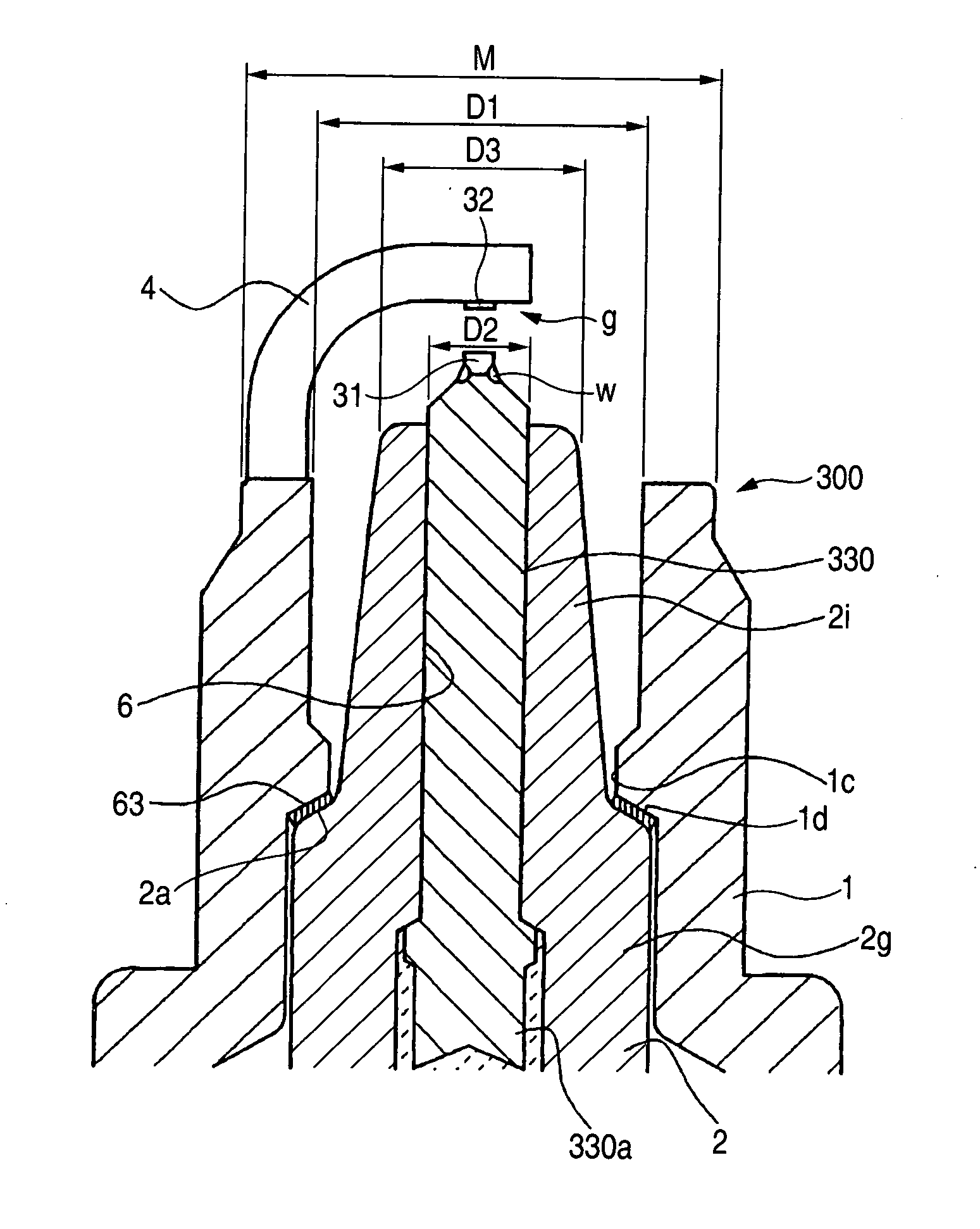
Figure 1 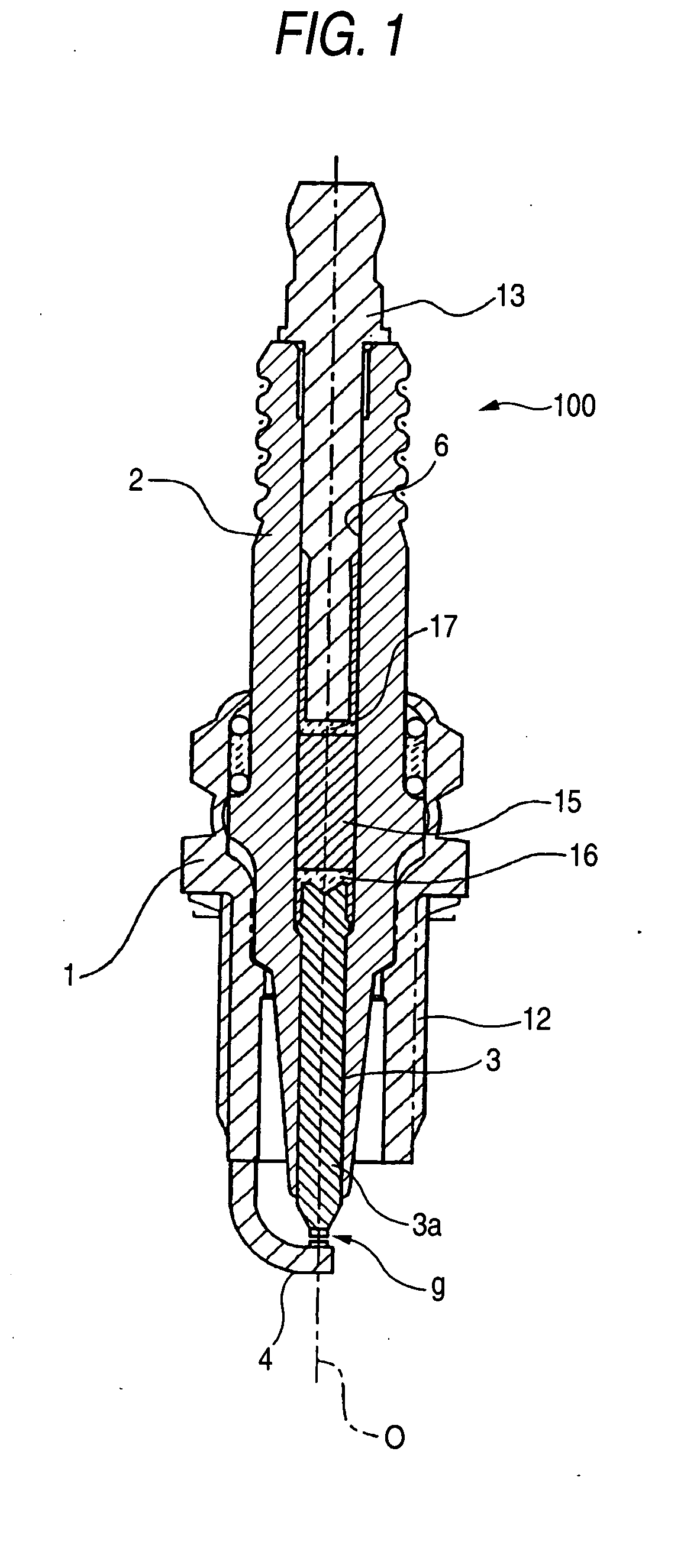
Figure 2 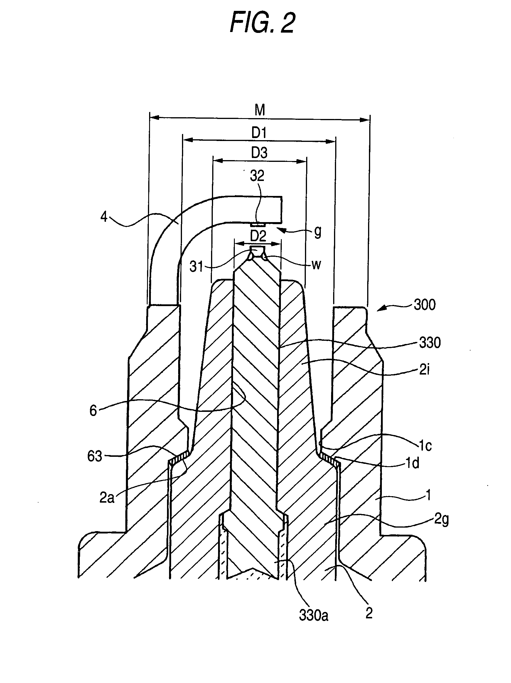
Figure 3
Abstract
Description
BACKGROUND OF THE INVENTION
[0001] 1. Field of the Invention
[0002] The present invention relates to a spark plug used for providing ignition of an internal combustion engine.
[0003] 2. Description of the Related Art
[0004] As a spark plug used for providing ignition of an internal combustion engine such as an automotive engine, many spark plugs of the type in which a noble metal chip consisting primarily of Pt, Ir, or the like is welded to a tip end of an electrode have been proposed. This configuration is employed because a discharge portion of the spark plug is arranged so as to protrude into a combustion chamber in order to enhance ignitability of the spark plug, and hence the discharge portion is exposed to a high temperature.
[0005] Recently, engine heads tend to have a complicated structure, and a space which is in the vicinity of a valve, and in which a spark plug is to be mounted, is reduced. Therefore, there is an increasing demand for a small spark plug in which the outer...
Examples
embodiment 1
[0052] Hereinafter, several embodiments of the invention will be described with reference to the accompanying drawings. However, the present invention should not be construed as being limited thereto.
[0053] A resistor-containing spark plug 100 shown in FIGS. 1 and 2 is an example of the invention, and comprises: a cylindrical metal shell 1, an insulator 2 which is fitted into the metal shell 1 so that a tip end portion protrudes therefrom; a center electrode 3 which is disposed inside the insulator 2 while projecting a discharge portion 31; and a ground electrode 4 which is placed so as to oppose a side face of the sparking portion 31 (the center electrode 3). The ground electrode 4 is bent so that the tip end face opposes the side face of the discharge portion 31 in a substantially parallel manner, and a discharge portion 32 is formed opposed to the discharge portion 31. A gap between the discharge portions 31 and 32 forms spark gap g. By contrast, a rear end portion of the ground...
embodiment 2
[0060] Next, Embodiment 2 of the invention will be described with reference to the accompanying drawings.
[0061] A spark plug 200 shown in FIG. 3 has a structure in which the tip end of the insulator 2 of the above-described spark plug 100 is modified so as to protrude from the tip end of the metal shell 1, and the tip end of the insulator 2 is positioned on the rear end side with respect to the tip end of the metal shell 1. In FIG. 3, components identical with those of FIG. 2 are denoted by the same reference numerals. This embodiment is configured in the same manner as Embodiment 1 except for the above-described positional relationships. In the following description, therefore, the positional relationships between the insulator and the metal shell will mainly be discussed.
[0062] In the spark plug 200 of Embodiment 2, the tip end of the, insulator 2 is positioned on the rear end side with respect to the tip end of the metal shell 1, and, when the outer diameter of the tip end of t...
embodiment 3
[0063] Next, Embodiment 3 of the invention will be described with reference to the accompanying drawings.
[0064] A spark plug 300 shown in FIG. 4 has a structure in which the center electrode 3 of the above-described spark plug 100 is configured in a different manner. In FIG. 4, components identical with those of FIG. 2 are denoted by the same reference numerals. This embodiment is configured in the same manner as Embodiment 1 except for the above-described positional relationships. In the following description, therefore, the positional relationships between the insulator and the metal shell will mainly be discussed.
[0065] A center electrode 330 is configured by the discharge portion 31, a skin layer 330a, and a core 330b. The skin layer 330a is made of an Ni alloy, specifically, an Ni alloy such as INCONEL 600 (trademark of INCO Limited). At the tip end of the insulator, the skin layer has a thickness of 5 μm or more. A noble metal chip of a circular plate-like shape constituting...