
Solid polymer type fuel cell, metal separator for fuel cell, and kit for fuel cell
Patent Information
- Authority / Receiving Office
- US · United States
- Current Assignee / Owner
- Publication Date
- 2005-12-15
- Estimated Expiration
- Not applicable · inactive patent
Smart Images
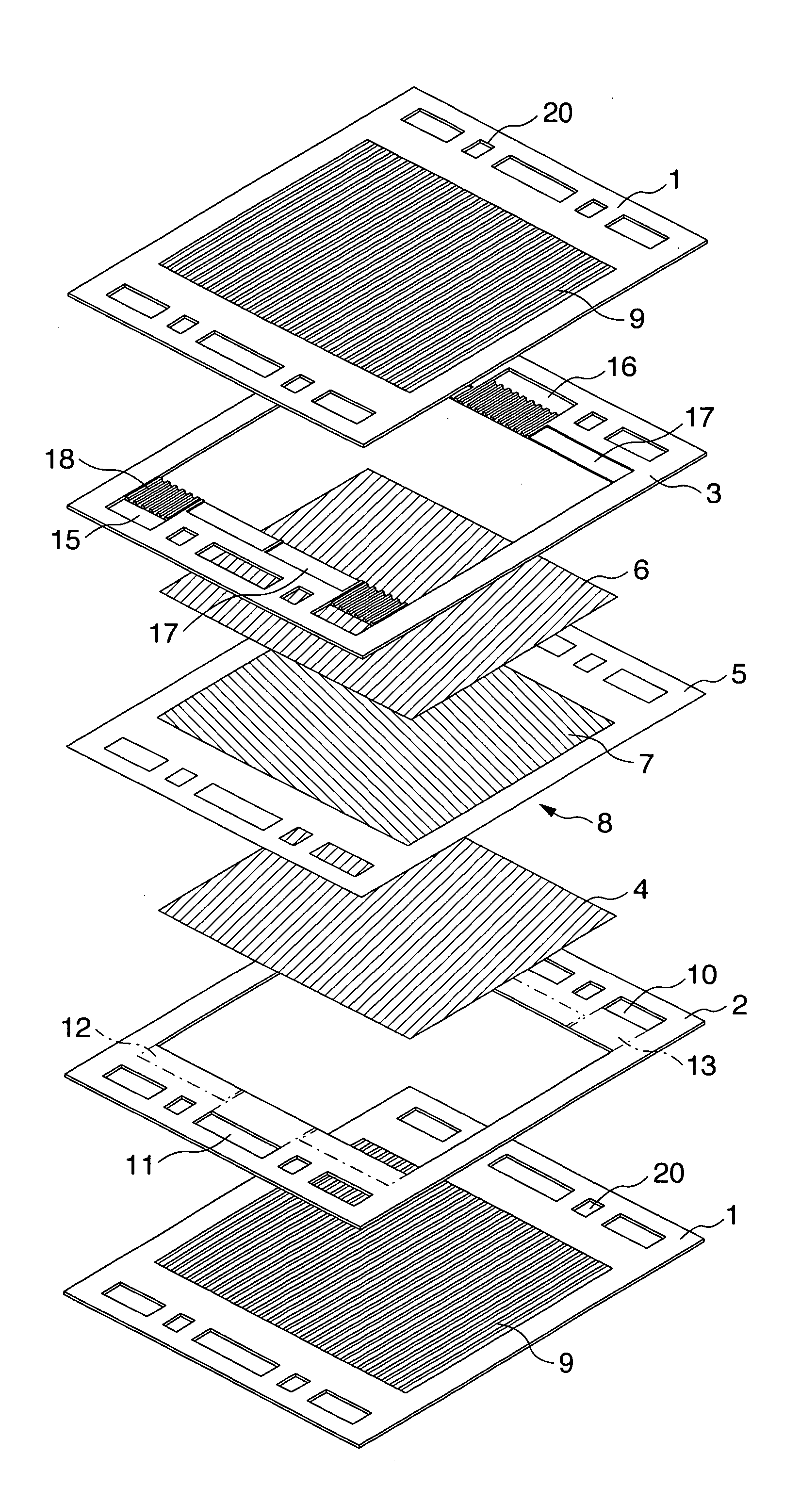
Figure 1 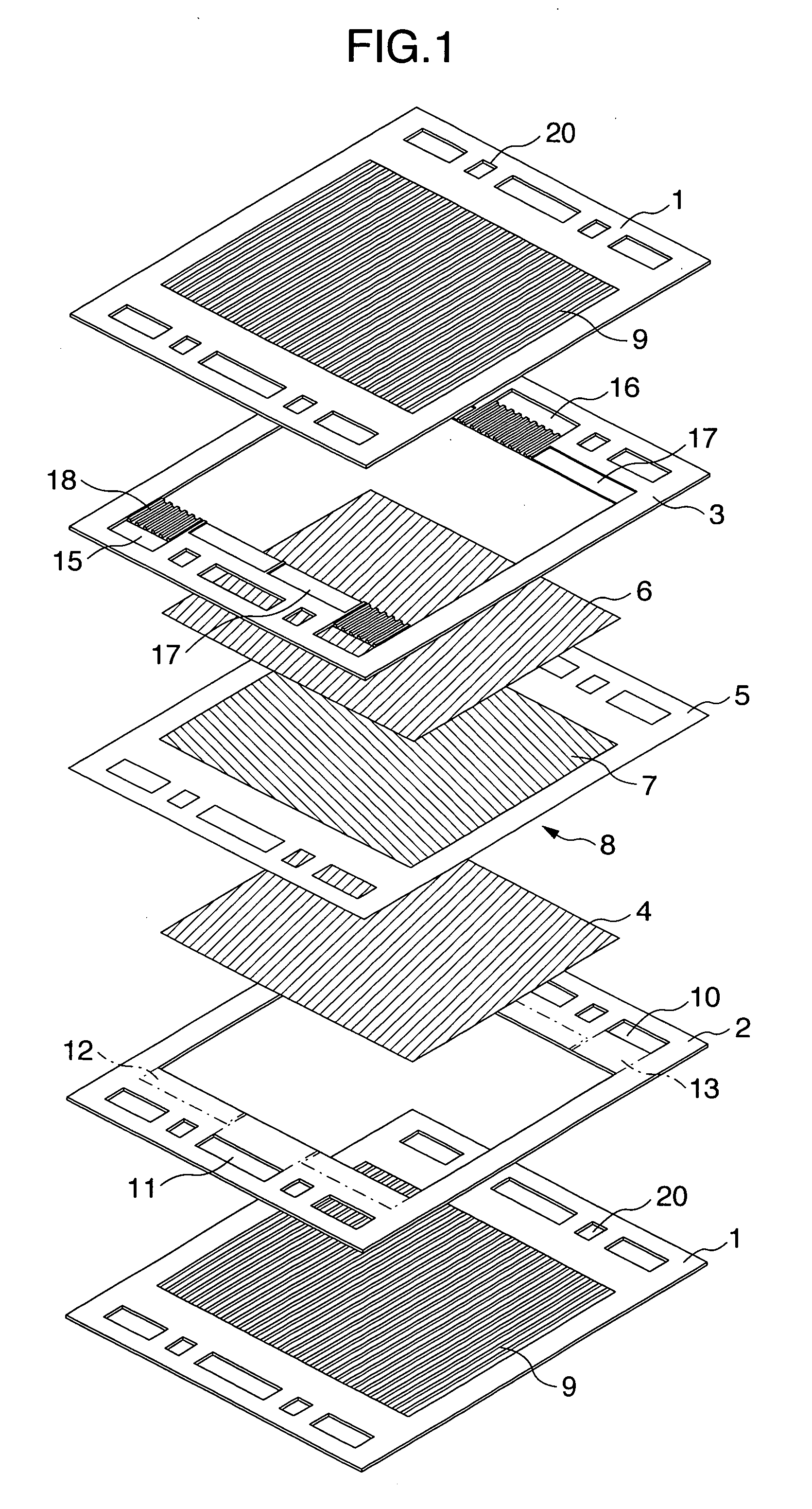
Figure 2 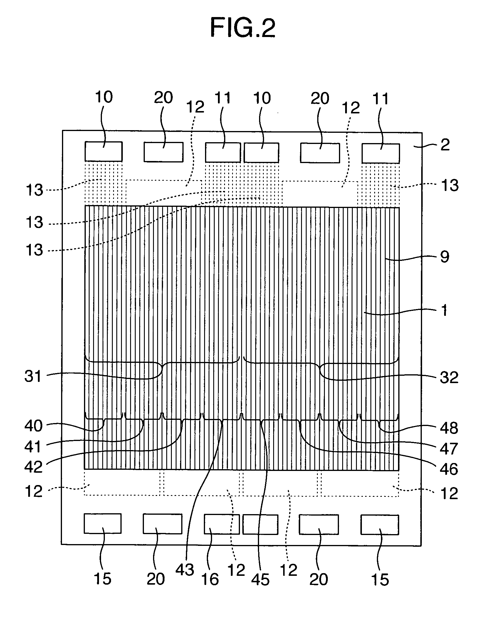
Figure 3
Abstract
Description
INCORPORATION BY REFERENCE
[0001] The present application claims priority from Japanese application JP 2004-175202 fled on Jun. 14, 2004, the content of which is hereby incorporated by reference into this application. BACKGROUND OF THE INVENTION
[0002] The present invention relates to a polymer electrolyte fuel cell capable of extracting energy from a fuel and an oxidant by means of an electrochemical reaction, a metallic separator for a fuel cell, and a kit for a fuel cell.
[0003] Polymer electrolyte fuel cells which use a proton-conducting polymer film as an electrolyte are a power generating system that is currently being researched. However, one problem to be resolved for practical use is high material costs. One of the high-cost materials which constitute a fuel cell is a separator. A separator segregates two reaction gases so that they do not mix, and is a term for an electron-conducting plate that is provided with gas channel grooves. When a fuel cell is generating power, the...
Examples
example 1
[0079] A 0.15 mm-thick stainless steel sheet having press-molded thereon 31 linear ridge / groove-shaped gas channels which had a gas channel pitch of 3 mm and an overhang of 0.3 mm was made to serve as a metal gas channel plate 1. On a 0.5 mm-thick sheet of PPS (polyphenylenesulfide) in which portions corresponding to the linear gas channels were in a hollowed out frame-shape, a cathode-side frame 2 was formed comprising a cathode gas supply manifold aperture 10, a cathode gas discharge manifold aperture 11, an anode gas supply manifold aperture 15, an anode gas discharge manifold aperture 16, a cathode turn-around portion 12, and three each of gas distribution channels A31 and distribution channels B32 for a total of 6 channels. The metal gas channel plate 1 and the frame 2 were adhered together using a liquid-state gasket so that there were no gaps therebetween, to thereby fabricate a cathode separator.
[0080] An external view of the cathode separator is illustrated in FIG. 2. In t...
example 2
[0086] A cathode-side frame 2 was formed comprising a cathode gas supply manifold aperture 10, a cathode gas discharge manifold aperture 11, an anode gas supply manifold aperture 15, an anode gas discharge manifold aperture 16, a cathode turn-around portion 12, and two each of gas distribution channels A31 and distribution channels B32 for a total of 4 channels. A metal gas channel plate 1 having linear ridge / groove-shaped gas channels 9 and the frame 2 were adhered together using a liquid-state gasket so that there were no gaps therebetween, to thereby fabricate a cathode separator. An external view of the cathode separator is illustrated in FIG. 3.
[0087] In this cathode separator, there are two gas distribution channels, gas distribution channel A31 and distribution channel B32, formed by the linear ridge / groove-shaped gas channels through which gas flows in the supply manifold, the discharge manifold and therebetween. Since each of the distribution channels 31 and 32 has 2 turn-...
example 3
[0088] A cathode-side frame 2 was formed comprising a cathode gas supply manifold aperture 10, a cathode gas discharge manifold aperture 11, an anode gas supply manifold aperture 15, an anode gas discharge manifold aperture 16, a cathode turn-around portion 12, and two each of gas distribution channels A31 and distribution channels B32 for a total of 4 channels. A metal gas channel plate 1 having linear ridge / groove-shaped gas channels 9 and the frame 2 were adhered together using a liquid-state gasket so that there were no gaps therebetween, to thereby fabricate a cathode separator. An external view of the cathode separator is illustrated in FIG. 4.
[0089] In this cathode separator, there are two gas distribution channels, gas distribution channel A31 and distribution channel B32, formed by the linear ridge / groove-shaped gas channels through which gas flows in the supply manifold, the discharge manifold and therebetween. Since each of the distribution channels 31 and 32 has 2 turn-...