
Optical scanning apparatus and image forming apparatus using same
an optical scanning and image forming technology, applied in the direction of inking apparatus, printing, instruments, etc., can solve the problems of deterioration in optical performance, complicated whole apparatus (high cost), and difficulty in setting the number of surfaces to 12. the effect of reducing the siz
Patent Information
- Authority / Receiving Office
- US · United States
- Patent Type
- Applications(United States)
- Current Assignee / Owner
- Publication Date
- 2006-09-14
- Estimated Expiration
- Not applicable · inactive patent
Smart Images
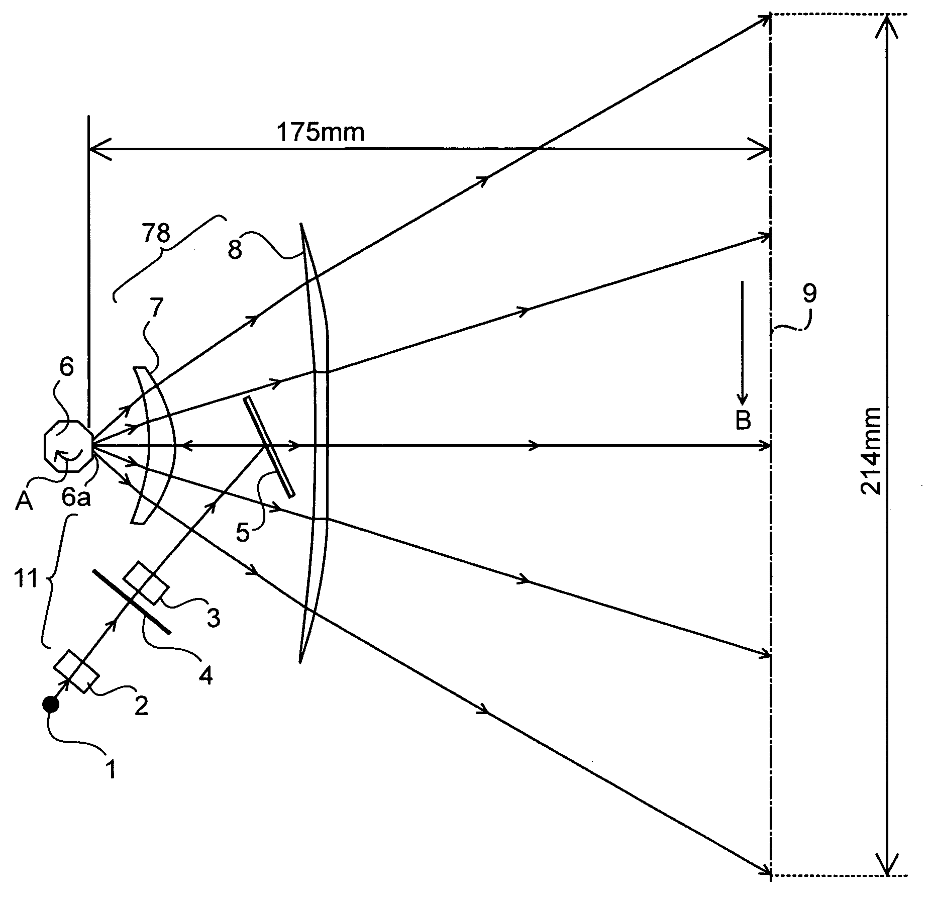
Figure 1 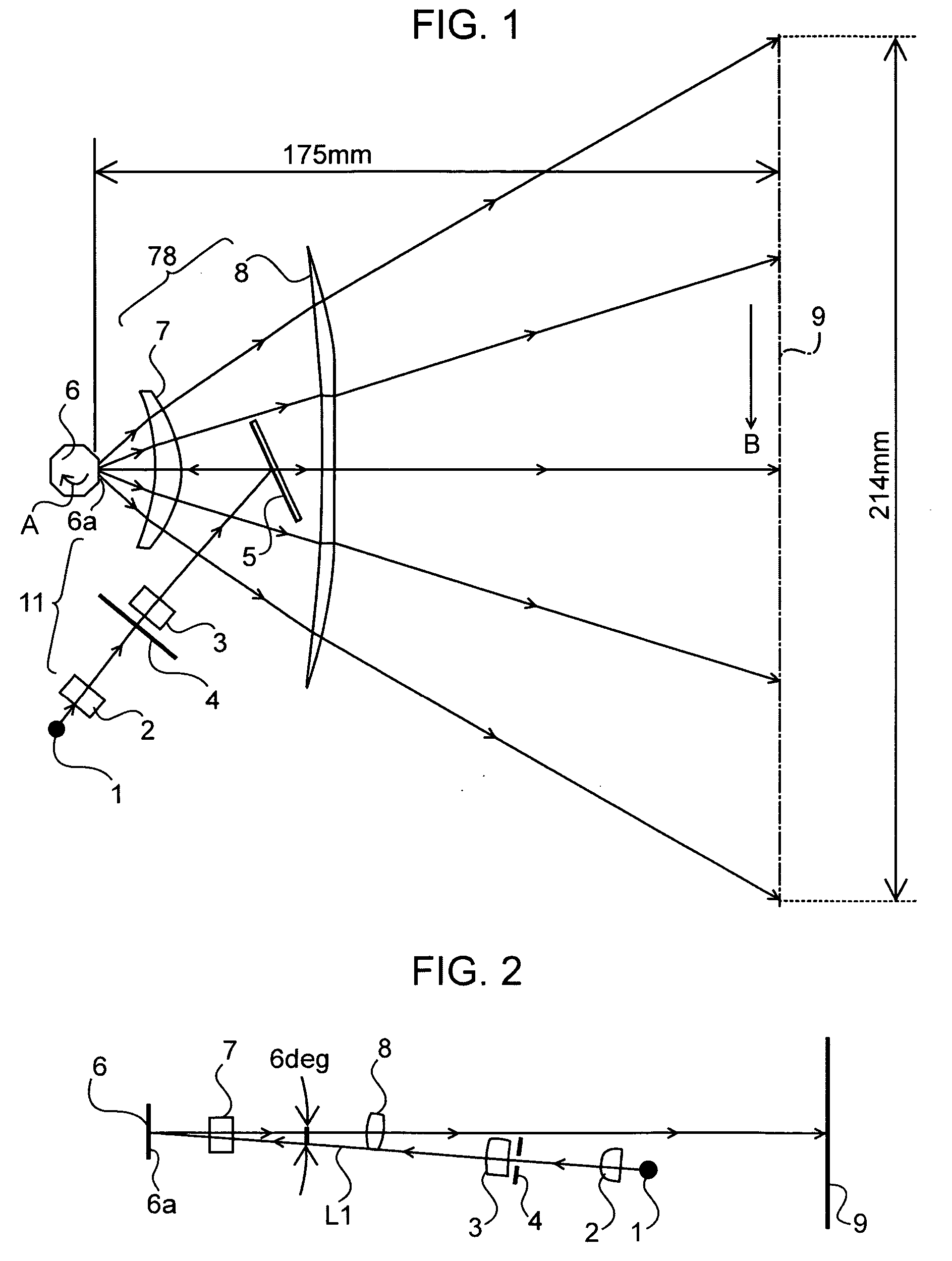
Figure 2 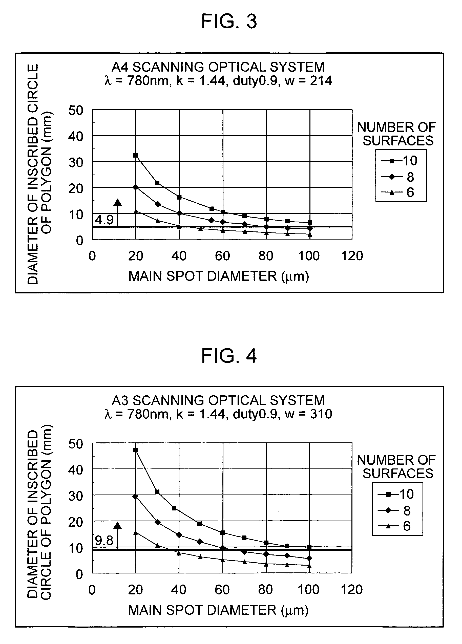
Figure 3
Abstract
Description
BACKGROUND OF THE INVENTION
[0001] 1. Field of the Invention
[0002] The present invention relates to an over-filled scanner (OFS) type optical scanning apparatus and an image forming apparatus using the same. More specifically, the present invention facilitates image forming apparatuses in which a light beam (laser beam) emitted from a light source device is reflected and deflected with a rotating polygon mirror serving as a light deflector, and a surface to be scanned is scanned with the light beam through an imaging optical system so as to record image information. Such image forming apparatuses are, for example, laser beam printers, digital photocopiers, and multifunctional printers that have an electro-photographic process.
[0003] 2. Description of the Related Art
[0004] An optical scanning apparatus is commonly used as a scanning optical system for laser beam printers, digital photocopiers, multifunctional printers, and so on. Recently, with the spread of these apparatuses, the...
Examples
exemplary embodiment 1
[0035]FIG. 1 is a schematic sectional view of an optical scanning apparatus according to exemplary embodiment 1 of the present invention in the main scanning direction (main scanning sectional view). FIG. 2 is a schematic sectional view of the optical scanning apparatus according to exemplary embodiment 1 of the present invention in the sub-scanning direction (sub-scanning sectional view, however, development view with regard to the incident optical system).
[0036] Here, the term “main scanning direction” refers to a direction perpendicular to the rotation axis of the rotating polygon mirror (a direction in which a light beam is deflected by reflection (scanned by deflection) by the rotating polygon mirror as shown by arrow B in FIG. 1). The term “sub-scanning direction” refers to a direction parallel to the rotation axis of the rotating polygon mirror. The term “main scanning plane” refers to a plane that is parallel to the main scanning direction and includes the optical axis of t...
exemplary embodiment 2
[0078] Next, exemplary embodiment 2 will be described.
[0079] In the present exemplary embodiment, the difference from exemplary embodiment 1 is that the present invention is applied to an apparatus whose effective scanning width W is 310 mm (A3 size paper) or less. Other configurations and optical effects are the same as those of exemplary embodiment 1, and the same advantages are obtained.
[0080] In the present exemplary embodiment, when the number of deflecting surfaces of the rotating polygon mirror 6 is N, the effective scanning width on the surface 9 to be scanned is W (mm), the wavelength (center wavelength) of the light beam emitted from the light source device 1 is λ (μm), and the diameter of the inscribed circle of the rotating polygon mirror 6 is φ (μm), the following conditions are satisfied:
N≦10
W≦310 (mm)
(W×N×λ) / {φ·tan(π / N)}≦475 (μm) (2)
[0081] The following are examples of numeric values of the optical scanning apparatus in the present exemplary embodiment, which f...
exemplary embodiment 3
[0086] Next, exemplary embodiment 3 will be described.
[0087] In the present exemplary embodiment, the difference from exemplary embodiments 1 and 2 is that a light-quantity correcting device is provided in the optical path. The light-quantity correcting device can adjust the energy (light quantity) of the light beam that can form an image in the center of scanning on the surface to be scanned and the energy (light quantity) of the light beam that can form an image at either end of scanning on the surface to be scanned. Other configurations and optical effects are the same as those of exemplary embodiments 1 and 2, and the same advantages are obtained.
[0088] The light-quantity correcting device provided in the optical path is, for example, a device for moving the laser 1 and a collimator lens in a direction corresponding to the main scanning direction (in the direction perpendicular to the optical axis in the plane of the paper in FIG. 1), a device for inserting a gradation filter ...