
Structure element for an aircraft
Patent Information
- Authority / Receiving Office
- US · United States
- Current Assignee / Owner
- Publication Date
- 2006-12-07
- Estimated Expiration
- Not applicable · inactive patent
Smart Images
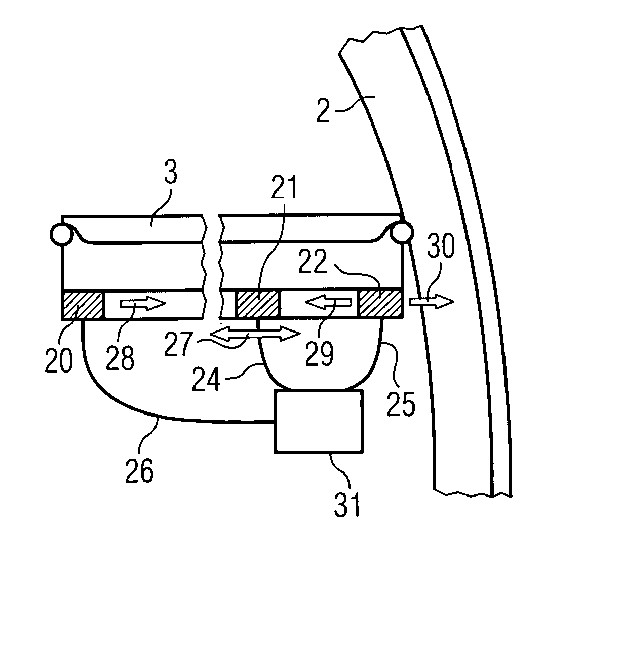
Figure 1 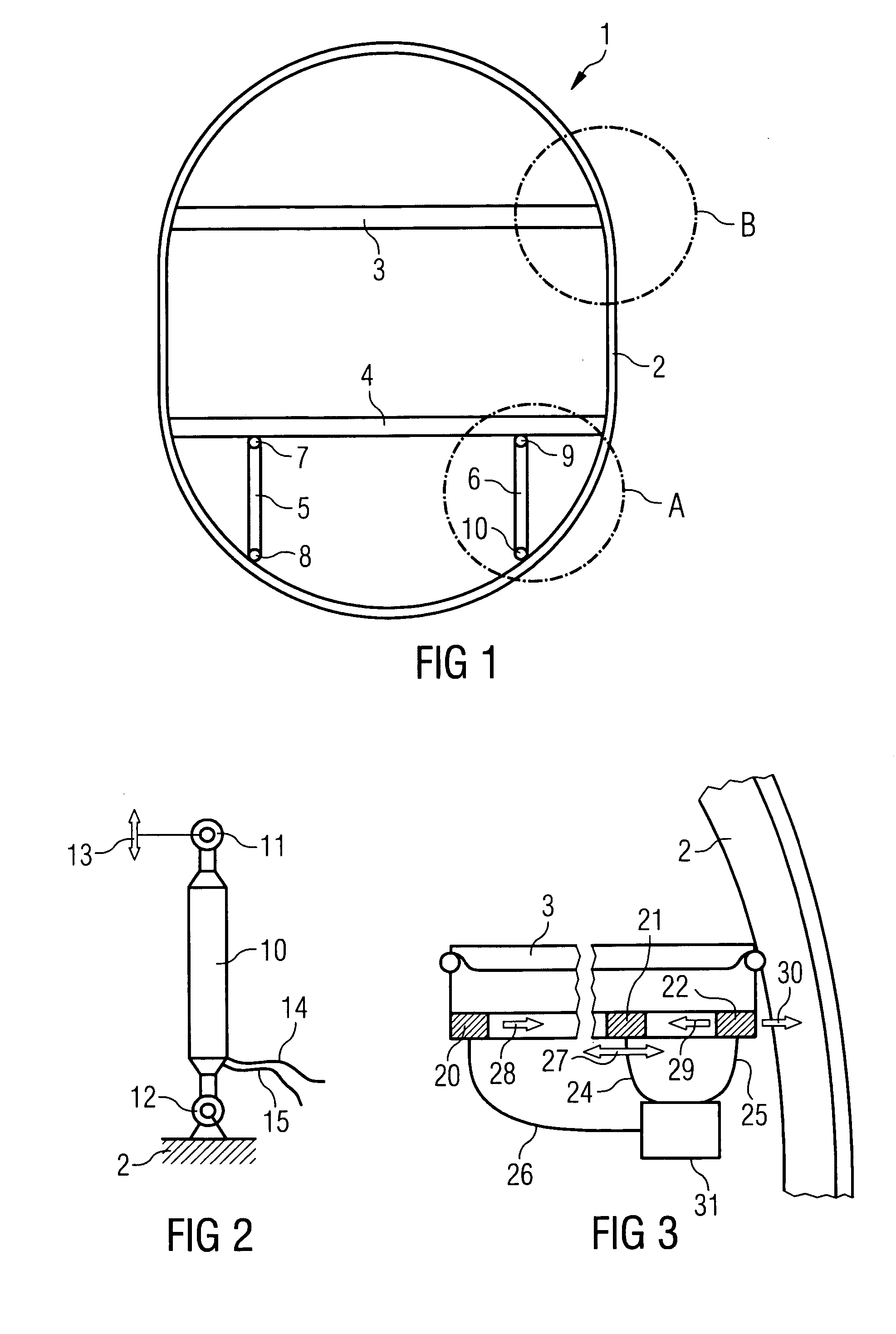
Figure 2
Abstract
Description
CROSS-REFERENCE TO RELATED APPLICATIONS
[0001] This application claims the benefit of the filing date of U.S. Provisional Patent Application No. 60 / 644,824 filed Jan. 18, 2006, the disclosure of which is hereby incorporated herein by reference.BACKGROUND OF THE INVENTION
[0002] The present invention relates to active structural elements of aircraft. In particular, the present invention relates to a structural element for an aircraft, comprising an active element and a passive element, an aircraft comprising a corresponding structural element, the use of a structural element in an aircraft, and a method for the active structuring of aircraft.
[0003] In the fuselage of aeroplanes, floor structures that comprise transverse floor girders and seat rails are connected to the frame on the right and left by means of rivets and are in turn supported vertically downward by the frame by way of so-called Samer rods. In this arrangement the seat rails extend transversely over the transverse gird...
Examples
Embodiment Construction
[0025] In the following description of the figures, the same reference characters are used for identical or similar elements.
[0026]FIG. 1 shows a diagrammatic cross-sectional representation of a fuselage. As is shown in FIG. 1 the fuselage 1 comprises an external skin 2 that is stabilised, supported and reinforced by transverse girders 3, 4 and Samer rods 5, 6. On the right-hand and left-hand sides the transverse girders 3, 4, which bear the floor structures in the fuselage, are connected to the aircraft frame (not shown in FIG. 1) by way of rivets. The Samer rods 5, 6 are used to support the transverse floor girder 4 downward on the frame. This construction is designed to achieve as stiff a floor as possible.
[0027] As a result of wind gusts or as a result of the engines, at times considerable forces are introduced into the aircraft structure, which forces can for example cause undesirable resonance oscillations or vibrations. These vibrations can at times cause significant noise ...