
Network fault diagnostic device, network fault diagnostic method, and computer product
Patent Information
- Authority / Receiving Office
- US · United States
- Current Assignee / Owner
- Publication Date
- 2007-03-29
- Estimated Expiration
- Not applicable · inactive patent
Smart Images
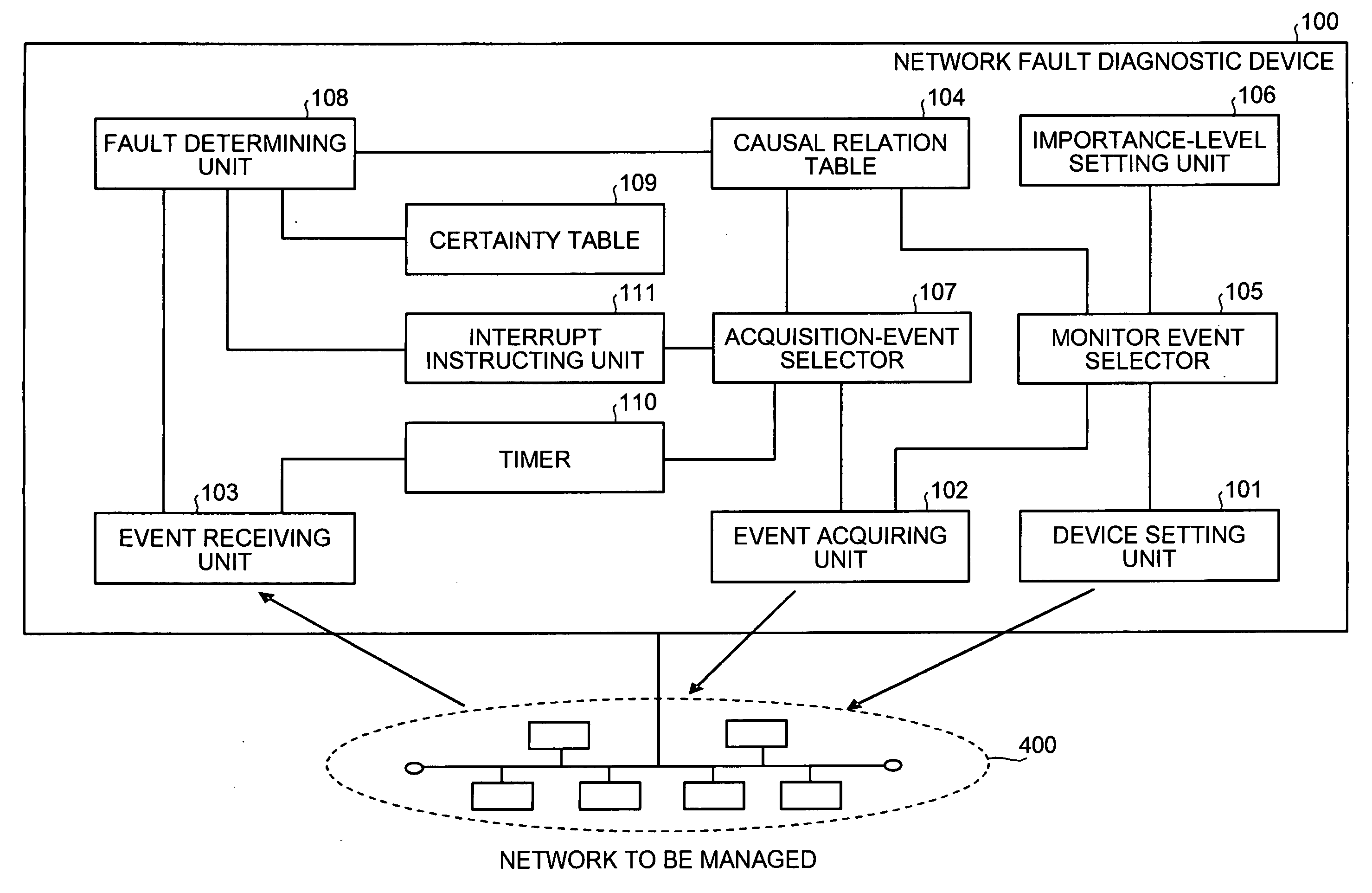
Figure 1 
Figure 2 
Figure 3
Abstract
Description
BACKGROUND OF THE INVENTION
[0001] 1. Field of the Invention
[0002] The present invention relates to a technology for identifying a fault based on a causal relation between a fault occurring on a network and an event indicating a sign of the fault.
[0003] 2. Description of the Related Art
[0004] Recently, networks are widely being used for exchanging and sharing information in various fields, and are becoming increasingly important. Therefore, it is extremely important to find out a fault as early as possible by always monitoring networks and preventing development of the fault to the vital state of the network.
[0005] Generally, automatic monitoring tools are used for network monitoring. The automatic monitoring tool collects events reported by a network device upon occurrence of a fault, analyses the events to identify the fault, and notifies a network administrator of the occurrence of the fault.
[0006] As an example of such automatic monitoring tools, U.S. Pat. No. 5,528,516 dis...
Examples
first embodiment
[0035]FIG. 1 is a functional block diagram of a network fault diagnostic device according to the present invention. A network fault diagnostic device 100 is connected to a network 400 to be managed being a target of which fault is monitored.
[0036] The network fault diagnostic device 100 includes a device setting unit 101, an event acquiring unit 102, an event receiving unit 103, a causal relation table 104, a monitor event selector 105, an importance-level setting unit 106, an acquisition-event selector 107, a fault determining unit 108, a certainty table 109, a timer 110, and an interrupt instructing unit 111.
[0037] The device setting unit 101 is a processor that sets a trap event selected by the monitor event selector 105, explained later, in each device connected to the network 400. Upon occurrence of a fault, when each device connected to the network 400 detects the trap event set in its own device, the device voluntarily transmits the trap event to the network fault diagnostic...
second embodiment
[0102]FIG. 16 is a functional block diagram of a network fault diagnostic device 200 according to the For convenience in explanation, the same reference numerals are assigned to functions that play the same roles as these in FIG. 2, and explanation thereof is omitted. As shown in FIG. 16, the network fault diagnostic device 200 is connected to the network 400 to be managed being a target of which fault is monitored.
[0103] The network fault diagnostic device 200 includes the device setting unit 101, the event acquiring unit 102, the event receiving unit 103, causal relation tables 2041 to 204n, the monitor event selector 105, the importance-level setting unit 106, the acquisition-event selector 107, the fault determining unit 108, the certainty table 109, a causal-relation-table dividing unit 212, a distribution table 213, an event history 214, a learning unit 215, and an event transformer 216.
[0104] The causal relation tables 2041 to 204n are memory units that store causal relatio...