
Sheet conveying device and image forming apparatus
Patent Information
- Authority / Receiving Office
- US · United States
- Current Assignee / Owner
- Publication Date
- 2008-09-25
- Estimated Expiration
- Not applicable · inactive patent
Smart Images
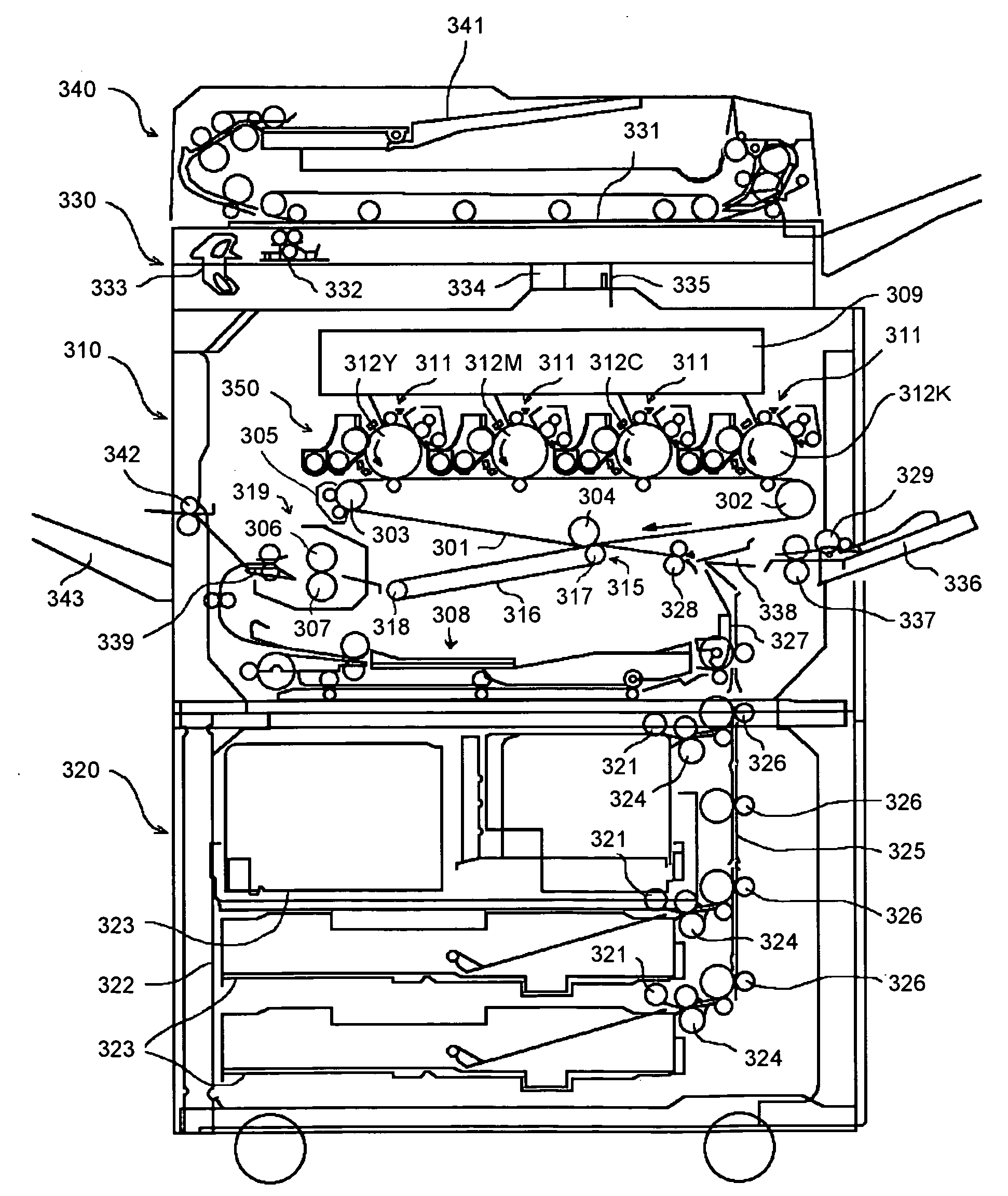
Figure 1 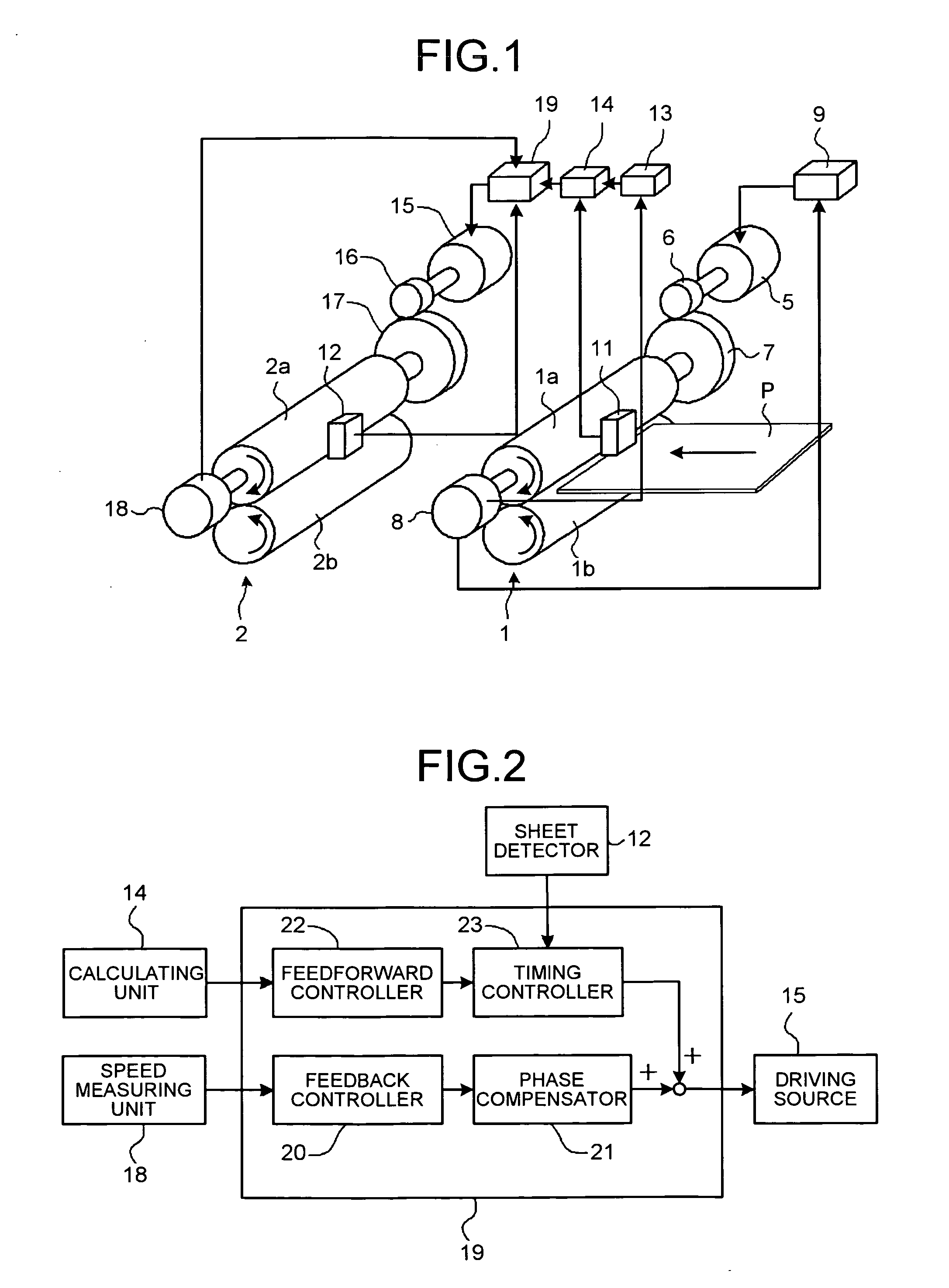
Figure 2 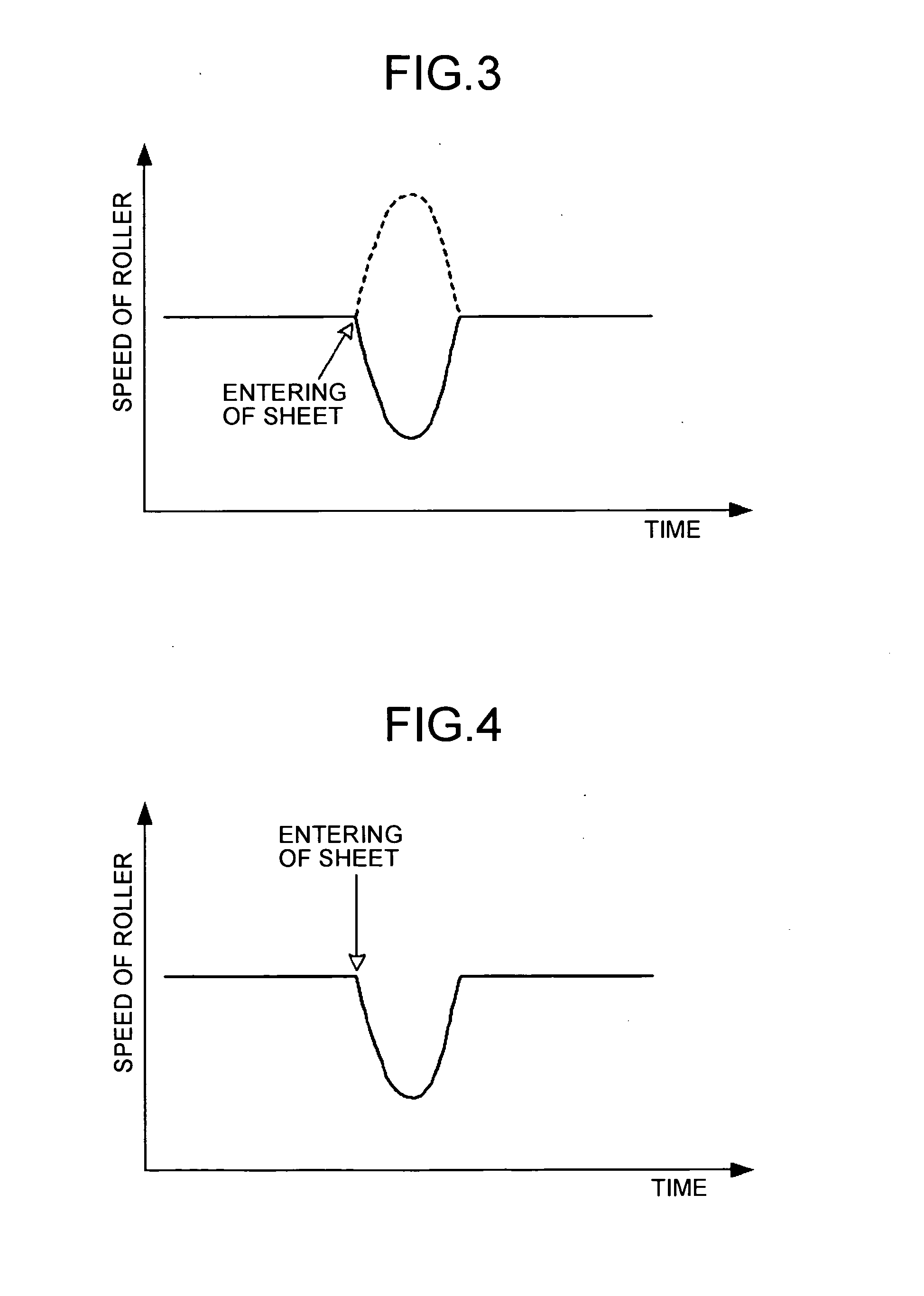
Figure 3
Abstract
Description
CROSS-REFERENCE TO RELATED APPLICATIONS
[0001] The present application claims priority to and incorporates by reference the entire contents of Japanese priority documents 2007-074551 filed in Japan on Mar. 22, 2007 and 2007-288547 filed in Japan on Nov. 6, 2007.BACKGROUND OF THE INVENTION
[0002] 1. Field of the Invention
[0003] The present invention relates to a sheet conveying device and an image forming apparatus.
[0004] 2. Description of the Related Art
[0005] Intermediate transfer type color image forming apparatuses are widespread in use. In such image forming apparatuses, a toner image each formed on a photosensitive element is primarily transferred onto an intermediate transfer member, and a color image on the intermediate transfer member is secondarily transferred onto a recording medium (sheet). The image forming apparatuses can be used for various types of sheet media such as thin sheet, thick sheet, postcard, and envelope, and therefore has an advantage of having high versatility. ...
Examples
Embodiment Construction
[0032]Exemplary embodiments of the present invention are explained in detail below with reference to the accompanying drawings.
[0033]FIG. 1 is a schematic diagram of a sheet conveying device according to a first embodiment of the present invention. The sheet conveying device of the first embodiment includes a pair of upstream rollers 1 as a first sheet conveying unit and a pair of downstream rollers 2 as a second sheet conveying unit. The pairs of rollers 1 and 2 each includes a drive roller 1a and a driven roller 1b, a drive roller 2a and a driven roller 2b. Sheet detectors 11 and 12 are respectively arranged near this side of the pairs of rollers 1 and 2. A recording medium (sheet) P is held between each pair of rollers 1 and 2, and conveyed from right to left in FIG. 1. The sheet conveying device can include three or more sheet conveying units.
[0034]The drive roller la in the upstream rollers 1 is driven by a motor (driving source) 5 via a small-diameter gear 6 and a large-diamet...