
Generating a data flow diagram
Patent Information
- Authority / Receiving Office
- US · United States
- Current Assignee / Owner
- Publication Date
- 2008-01-24
Smart Images
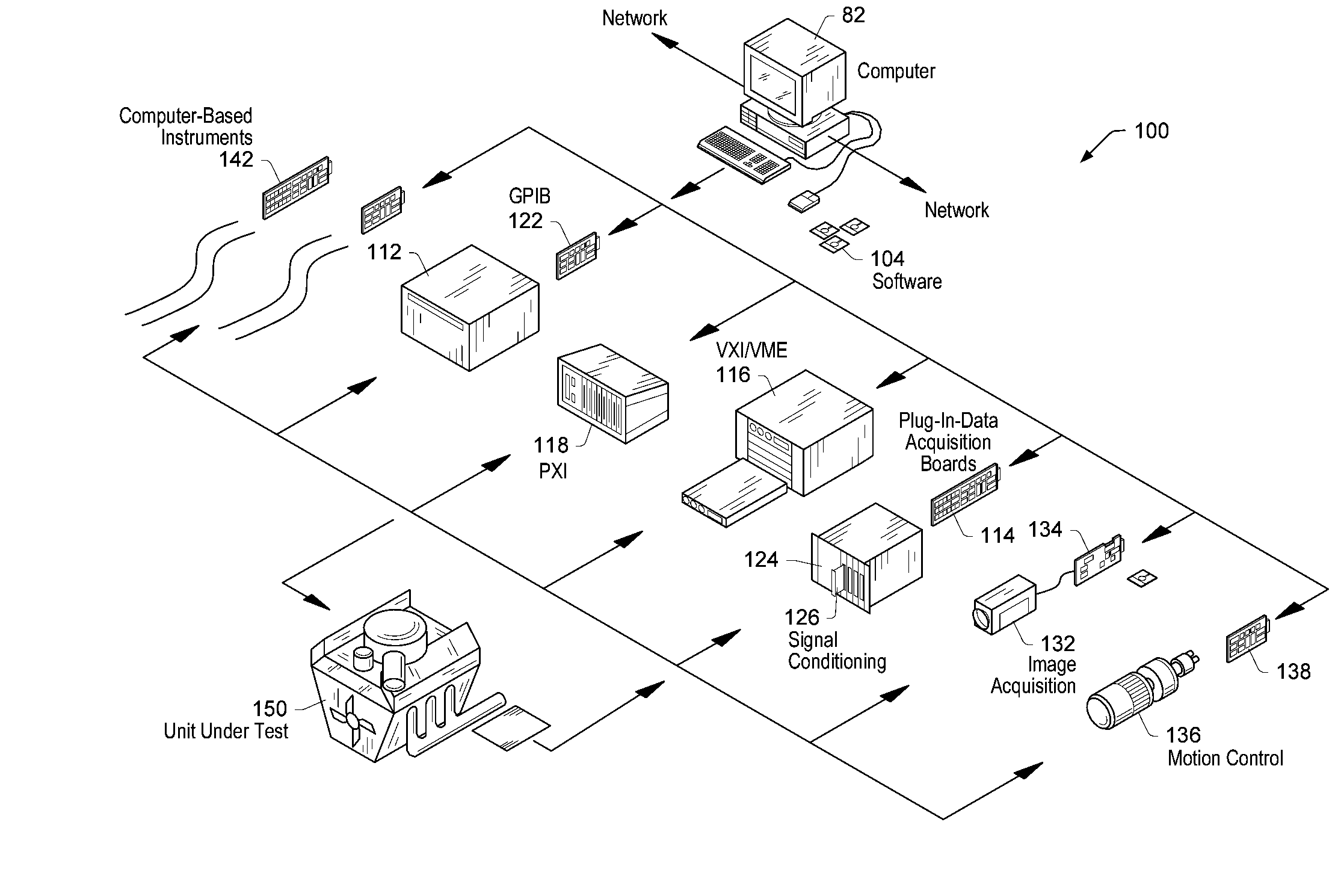
Figure 1 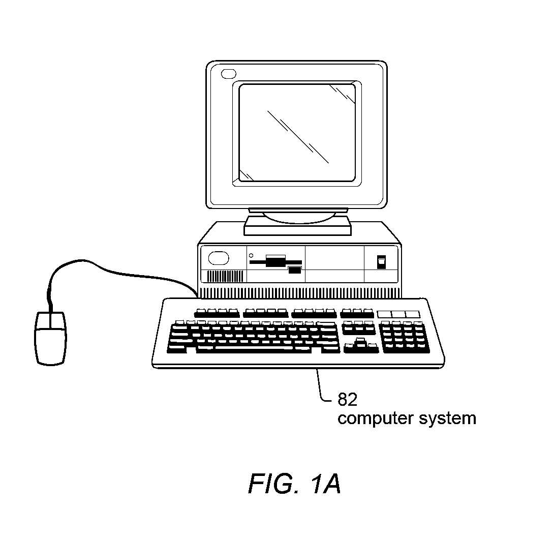
Figure 2 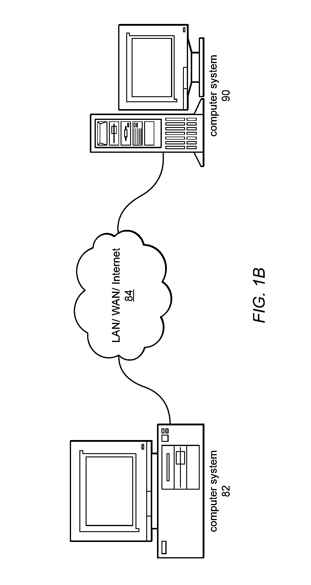
Figure 3
Abstract
Description
PRIORITY DATA
[0001] This application claims benefit of priority of U.S. provisional application Ser. No. 60 / 820,063 titled “Hierarchical Code Generation for Simulation Subsystems” filed Jul. 21, 2006, whose inventor was Kevin M. Hogan.FIELD OF THE INVENTION
[0002] The present invention relates to the field of graphical programming and more particularly to the generation of input bound data flow diagrams from non-input bound data flow diagrams. DESCRIPTION OF THE RELATED ART
[0003] Various graphical programming environments now exist which allow a user to construct a graphical program or graphical diagram, also referred to as a block diagram. U.S. Pat. Nos. 4,901,221; 4,914,568; 5,291,587; 5,301,301; and 5,301,336; among others, to Kodosky et al. disclose a graphical programming environment which enables a user to easily and intuitively create a graphical program. Graphical programming environments such as that disclosed in Kodosky et al. can be considered a higher and more intuitiv...
Examples
Embodiment Construction
Incorporation by Reference
[0044] The following references are hereby incorporated by reference in their entirety as though fully and completely set forth herein:
[0045] U.S. Provisional Application Ser. No. 60 / 820,063 titled “Hierarchical Code Generation for Simulation Subsystems” filed Jul. 21, 2006.
[0046] U.S. Provisional Application Ser. No. 60 / 571,205 titled “Graphical Data Flow Programming Environment with First Model of Computation that Includes a Structure Supporting Second Model of Computation”, filed May 14, 2004.
[0047] U.S. Pat. No. 4,914,568 titled “Graphical System for Modeling a Process and Associated Method,” issued on Apr. 3, 1990.
[0048] U.S. Pat. No. 5,481,741 titled “Method and Apparatus for Providing Attribute Nodes in a Graphical Data Flow Environment”.
[0049] U.S. Pat. No. 6,219,628 titled “System and Method for Converting Graphical Programs Into Hardware Implementations” filed Mar. 22, 2000.
[0050] U.S. Pat. No. 6,173,438 titled “Embedded Graphical Programm...