
Membrane Grating for Beam Steering Device and Method of Fabricating Same
Patent Information
- Authority / Receiving Office
- US · United States
- Current Assignee / Owner
- Publication Date
- 2008-10-09
- Estimated Expiration
- Not applicable · inactive patent
Smart Images
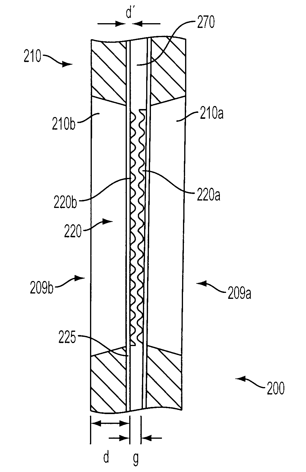
Figure 1 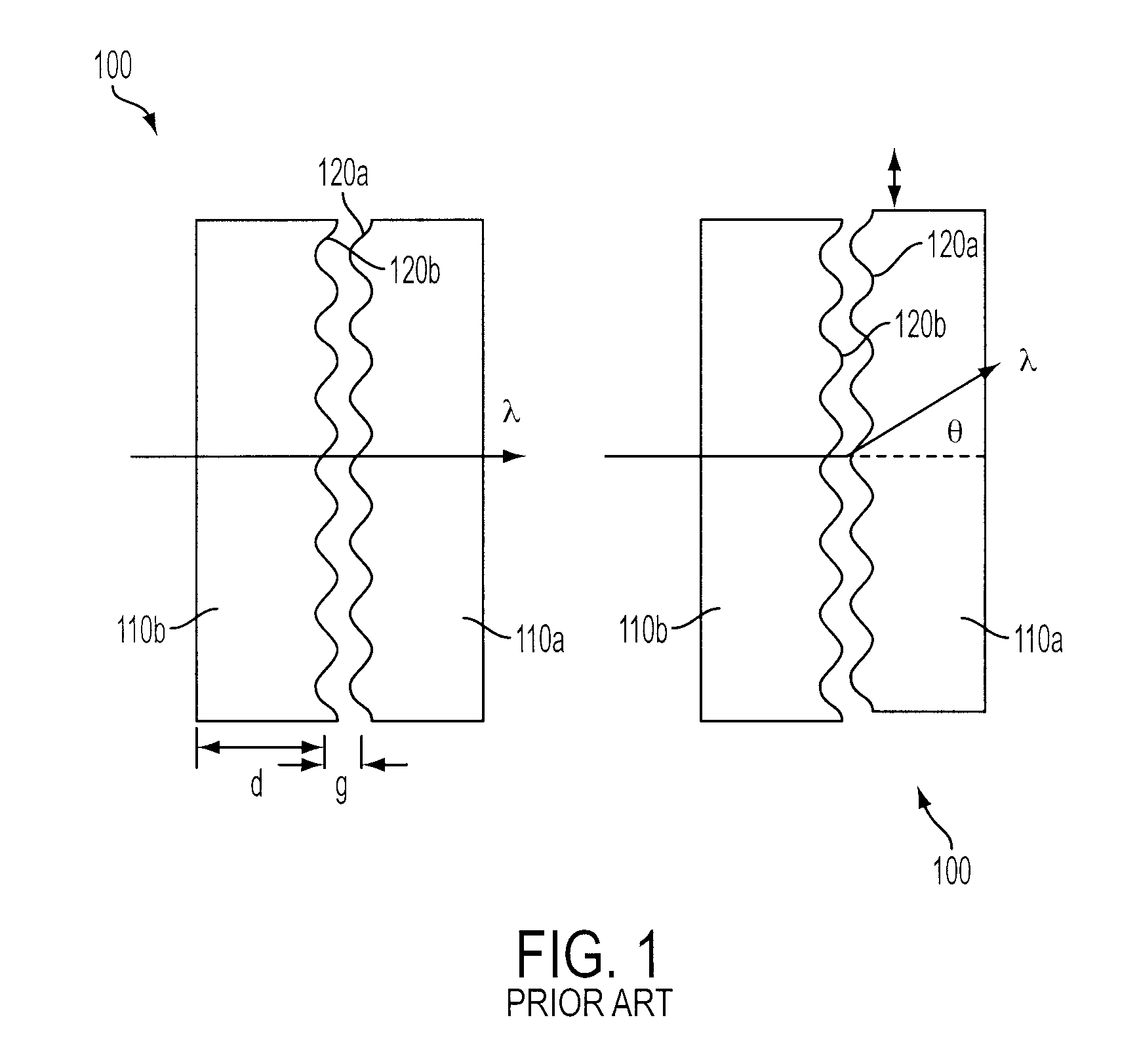
Figure 2 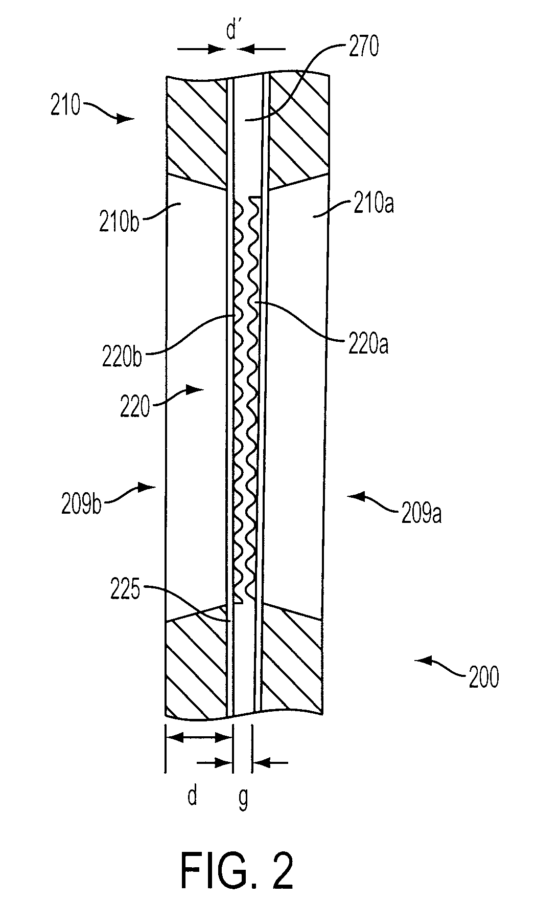
Figure 3
Abstract
Description
CROSS-REFERENCE TO RELATED APPLICATIONS
[0001] This Application claims the benefit of priority of U.S. Provisional Patent Application No. 60 / 922,128, filed Apr. 6, 2007, which application is hereby incorporated by reference in its entirety.BACKGROUND
[0002] 1. Field of the Invention
[0003] The subject invention is directed to a diffractive phased array assembly used as a beam steering device in an optical system, and to a method of fabricating and constructing such an assembly.
[0004] 2. Description of Related Art
[0005] Diffractive phased array assemblies are used as beam steering devices in many optical systems such as bar code scanners, laser machining applications and laser printers, as discussed in U.S. Pat. No. 6,480,334 to Farn, the disclosure of which is herein incorporated by reference in its entirety.
[0006] A known diffractive phased array design used as a beam steering device in LIDAR (Laser Imaging Detection and Ranging) applications is formed from 2-inch square silicon plates. The...
Examples
Embodiment Construction
[0037]The benefits of the subject invention are shown in FIGS. 3a-3b, which compare a conventional diffractive phased array plate assembly 103 to an assembly 300 having membrane structures formed by a method in accordance with the subject invention. FIG. 3a illustrates a realistic case where the substrates 110a, 110b are slightly warped, demonstrating the difficulty in maintaining relatively small uniform plate spacing. For example, the plates could be in intimate contact at one location 2, while the gap between the plates could be tens of microns or larger at another location 1.
[0038]FIG. 3b illustrates how the two patterned gratings can be brought into operative uniform contact using a membrane grating approach. If the net strain of the combined structure is such that the thin film membrane layer 225 is pulled tightly across a window 209a, 209b formed in the substrate 210a, 210b, it will no longer exhibit the curvature of the substrate 210a, 210b. While this serves to reduce or el...