
Screw tightening apparatus
a screw and tightening technology, applied in the direction of wrenches, metal-working apparatus, measuring torque/twisting force while tightening, etc., can solve the problem of difficult to precisely form a key groove on the output shaft, the transmission of sufficient torque from the hollow gear may be impossible, and the pitch of the screw is narrower. , to achieve the effect of convenient processing, good conductivity and sufficient torqu
Patent Information
- Authority / Receiving Office
- US · United States
- Patent Type
- Applications(United States)
- Current Assignee / Owner
- Publication Date
- 2008-12-25
- Estimated Expiration
- Not applicable · inactive patent
Smart Images
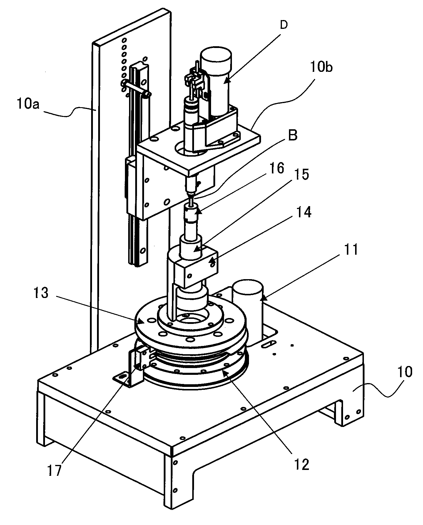
Figure 1 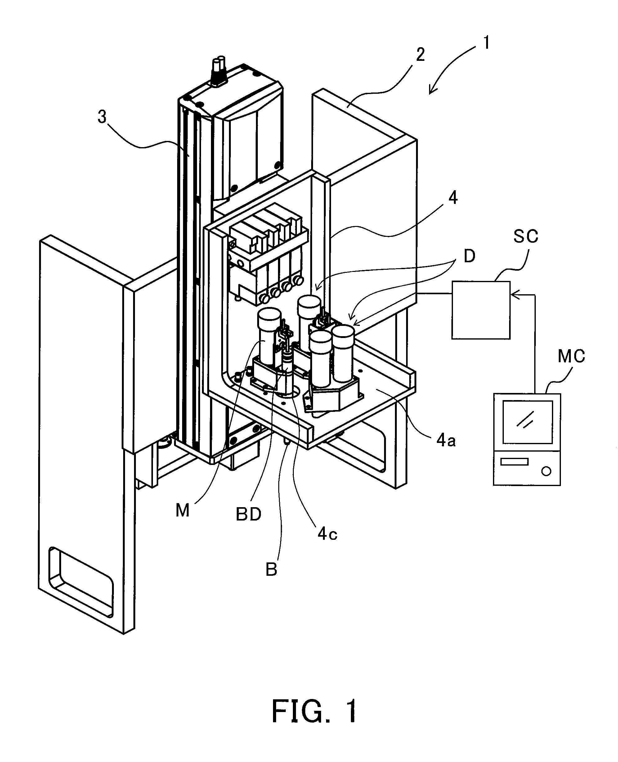
Figure 2 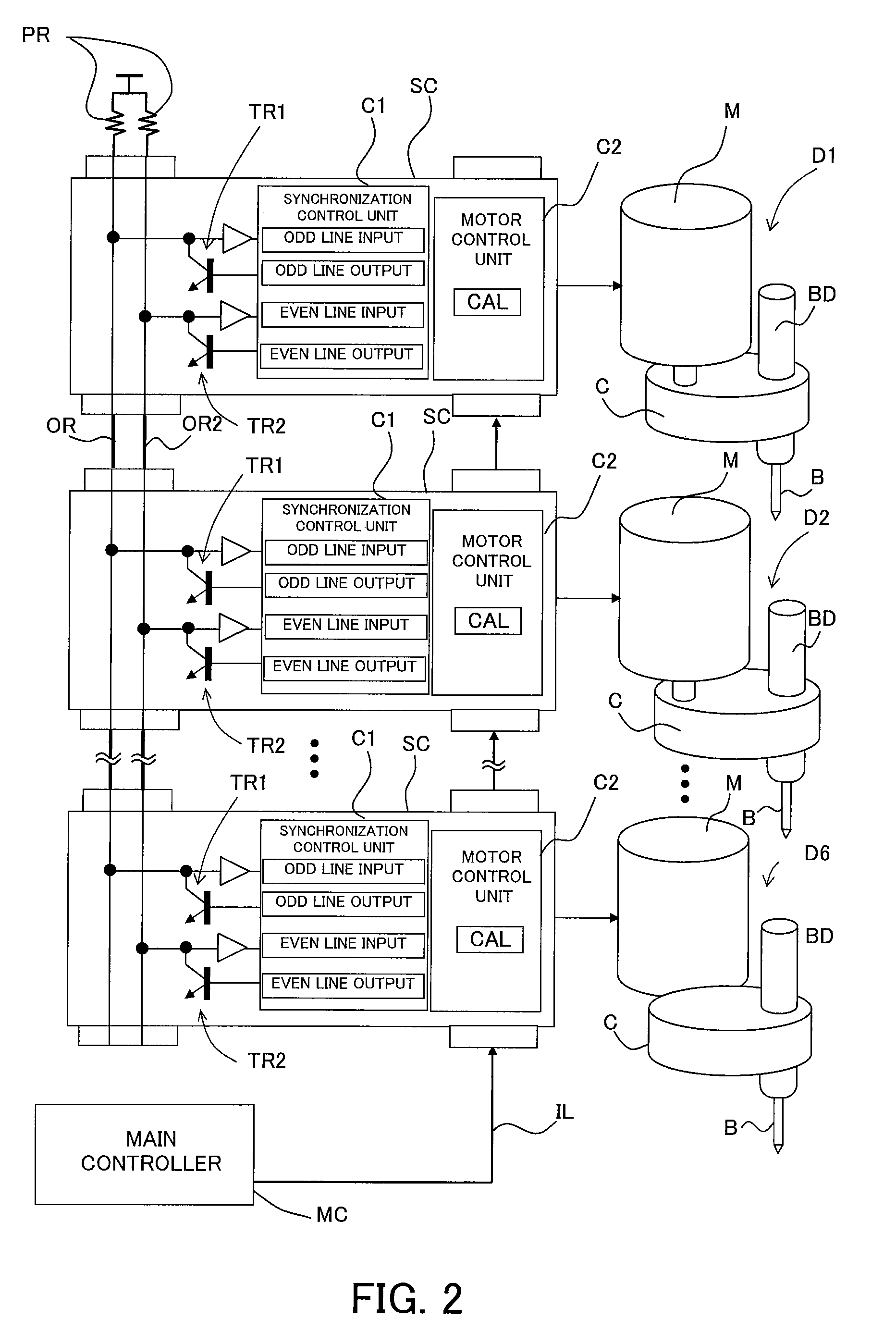
Figure 3
Abstract
Description
[0001] This application is a continuation based on International Patent Application No. PCT / JP2006 / 0303913, filed on Mar. 1, 2006, which is hereby incorporated by reference herein in its entirety as if fully set forth herein.BACKGROUND OF THE INVENTION
[0002] The present invention relates to a screw tightening apparatus that tightens a screw by motor driving.
[0003] Screw tightening apparatuses include one in which a motor serving as a driving source and a bit engaging with a recess of a screw are offset in their radial direction (for example, refer to Japanese Patent Laid-Open No. 2003-25164). In many cases, such a so-called offset-type screw tightening apparatus is used in, for example, a case in which a plurality of screw tightening apparatuses are disposed so as to be adjacent to one another, to collectively performing the tightening of a plurality of screws disposed with a pitch narrower than a pitch between the motors.
[0004] Further, in such an offset-type screw tightening apparatus...
Examples
embodiment 1
[0048]FIG. 1 illustrates the schematic configuration of a screw tightening system that is Embodiment 1 of the present invention. Reference numeral 1 denotes the entire screw tightening system of this embodiment. Reference numeral 2 denotes a main body of the screw tightening system 1 (hereinafter referred to as an apparatus main body). Reference numeral 3 denotes a lifting mechanism attached to the apparatus main body 2, the lifting mechanism moving a support table 4 up and down.
[0049]Plural (four in FIG. 1) screw tightening drivers (screw tightening apparatuses) D are attached on a horizontal plate 4a of the support table 4. Each of these screw tightening drivers D rotates a screw tightening bit B extending downward from the horizontal plate 4a through a through-hole 4c formed in the horizontal plate 4a. These screw tightening drivers D perform screw tightening operations with respect to a workpiece (an object for screw tightening) (not shown) which is disposed beneath the horizont...
embodiment 2
[0135]FIG. 8 shows a control procedure and operation timings of the screw tightening operations by a screw tightening system that is Embodiment 2 of the present invention. This embodiment shows an example of the case in which five screws are tightened with respect to a workpiece such as the clamp plate 25 or the like by the first to fifth drivers D1 to D5 (hereinafter called the drivers 1 to 5) among all the drivers D1 to D6 described in Embodiment 1. Constituent components in this embodiment identical to those in Embodiment 1 are denoted by the same reference numerals as those in Embodiment 1.
[0136]Embodiment 1 described the case in which the start timings of the seating operations and the torque increase operations of the respective drivers after the synchronization had differences. However, this embodiment will describe a case where the seating operations and the torque increase operations of all the drivers after synchronization are simultaneously started.
[0137]In FIG. 8, (a) to...
embodiment 3
[0171]Embodiments 1 and 2 described the case where the synchronization control for the screw tightening drivers is performed by using the odd and even wired OR lines. However, the same synchronization control can be applied to a motor-driven apparatus other than the screw tightening drivers.
[0172]FIG. 9 illustrates a synchronization control system for performing position control of an object (a robot arm, a positioning table or the like) P in directions of four axes (X-, Y-, Z-, and θ-axes) which is Embodiment 3 of the present invention. Constituent components in this embodiment shown in FIG. 9 identical to those in Embodiment 1 are denoted by the same reference numerals as those in Embodiment 1. In this embodiment, synchronization control of motors MX, MY, MZ, and MO for drive in the directions of the X, Y, Z, and θ-axes in place of the screw tightening drivers in Embodiment 1 is performed.
[0173]FIG. 10 shows a control procedure and operation timings of this embodiment. This embodi...