
Hot compressed gas vehicle
a technology of compressed gas and hot air, which is applied in the direction of light-to-electric conversion, electric devices, transportation and packaging, etc., can solve the problems of low efficiency, no alternative system has come into widespread use, and low energy efficiency of internal combustion engine vehicles, so as to achieve less pollution, less complex, and more energy-efficient
Patent Information
- Authority / Receiving Office
- US · United States
- Patent Type
- Applications(United States)
- Current Assignee / Owner
- Publication Date
- 2009-11-26
- Estimated Expiration
- Not applicable · inactive patent
Smart Images
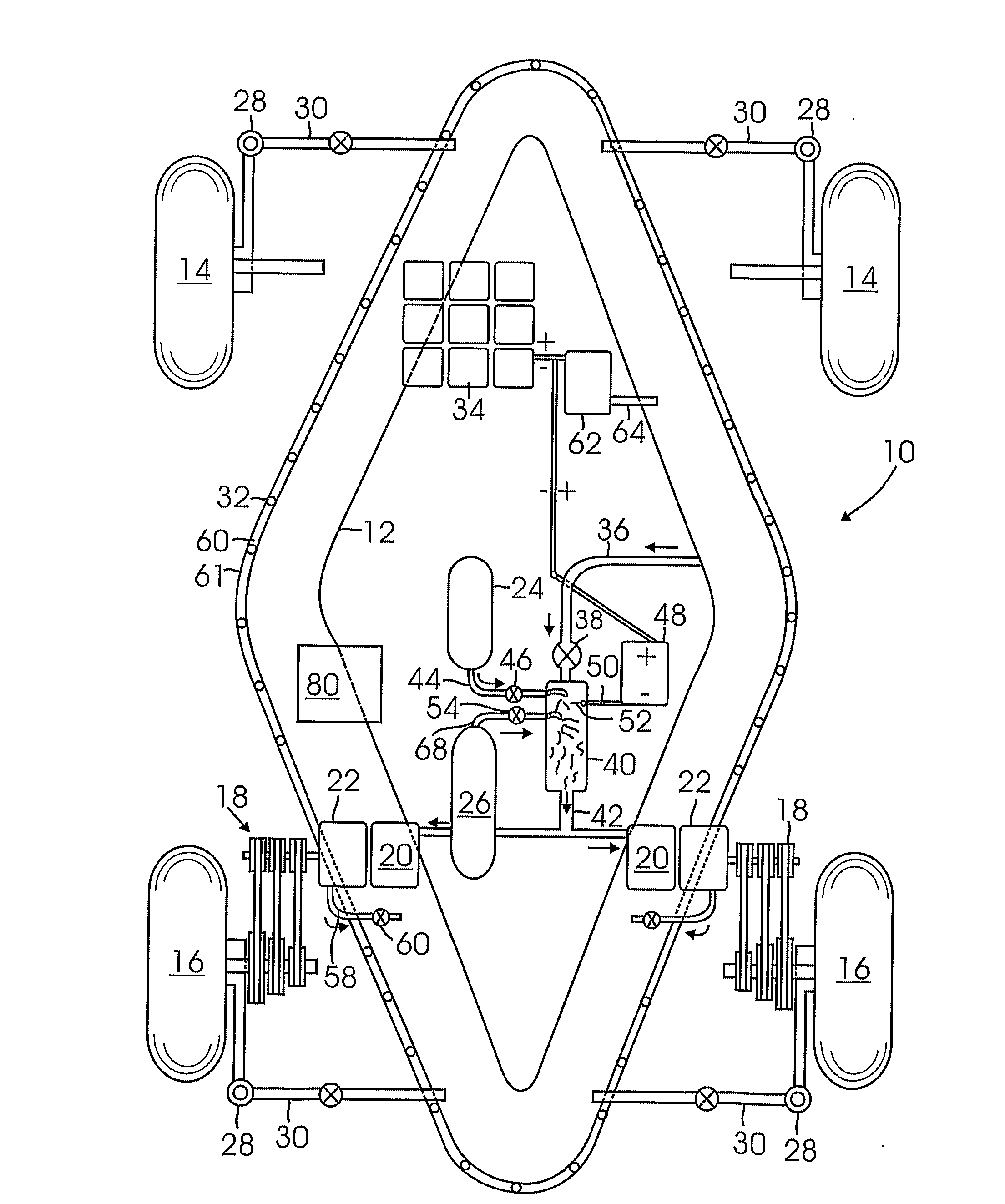
Figure 1 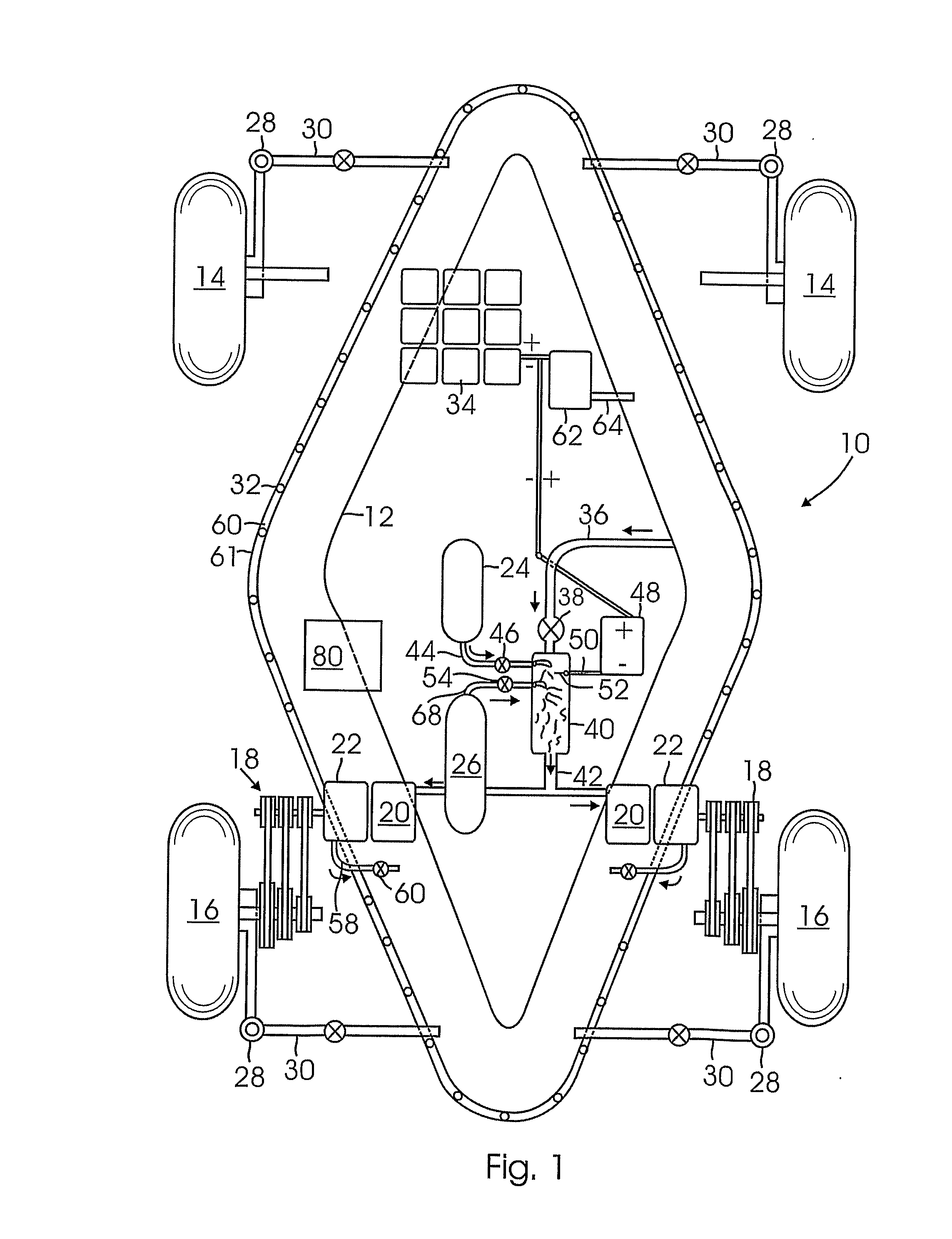
Figure 2 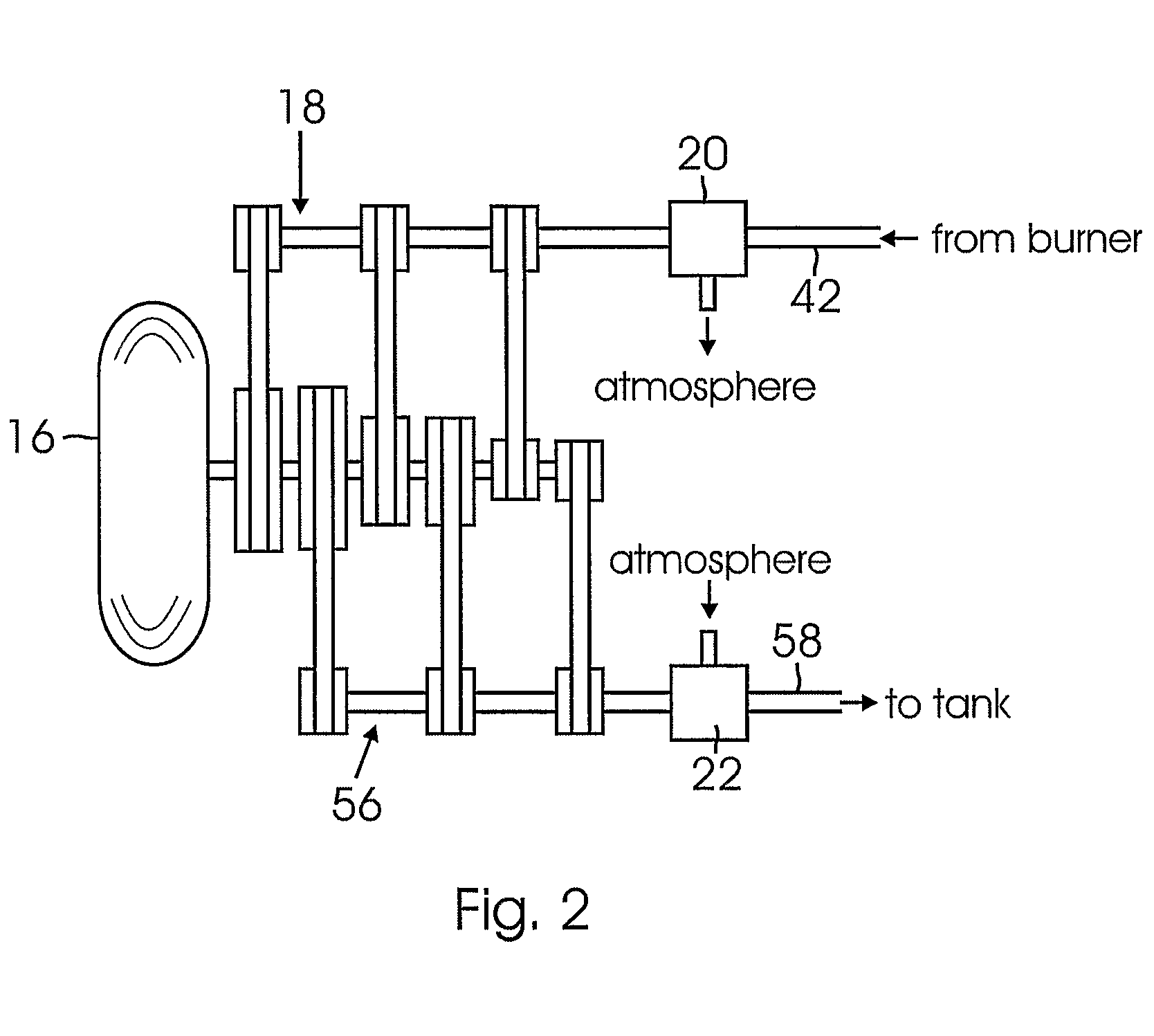
Figure 3
Abstract
Description
BACKGROUND OF THE INVENTION
[0001] 1. Field of the Invention
[0002] This invention relates to apparatus for powering a vehicle capable of carrying people, cargo, etc. in which the motive energy is derived from compressed air.
[0003] 2. Description of the Related Art
[0004] While most land vehicles, such as automobiles, trucks, etc. and many light aircrafts are powered by internal combustion engines, a number of other drive systems have been proposed. These include gas turbine engines, steam engines, electric battery power, etc. and combinations of these systems. Because of the high state of development of the internal combustion engine and certain problems with these alternative systems such as low efficiency, short range and other problems, none of these alternative systems have come into widespread use. Internal combustion engine vehicles have low energy efficiency. The main reason for this is that in the internal combustion engine, energy produced in the form of hot pressurized gas at co...
Examples
Embodiment Construction
[0028]FIG. 1 schematically illustrates a road vehicle 10 such as a passenger automobile or the like using an air powered drive system according to an embodiment of the present invention. An air tank 12 is provided for storing compressed air. In the illustrated example, the tank 12 surrounds the perimeter of a base of the vehicle and has a diamond shape with pointed ends at the front and rear. While this position is preferred since it provides an energy absorbing structure in the event of a collision, the tank 12 may have any suitable shape and can be located in any suitable position. Typically, the tank 12 can accommodate 100 to 1000 or more psi pressure and can be formed from any suitable material, such as metals, fiber reinforced plastics such as carbon fibers in a resin matrix, etc.
[0029]The vehicle 10 is supported on a plurality of conventional wheels. Here four wheels including two forward wheels 14 and two aft wheels 16 are shown. An air motor 20 through a variable speed trans...