
Hose joint clamp
Patent Information
- Authority / Receiving Office
- US · United States
- Current Assignee / Owner
- Publication Date
- 2010-12-09
- Estimated Expiration
- Not applicable · inactive patent
Smart Images
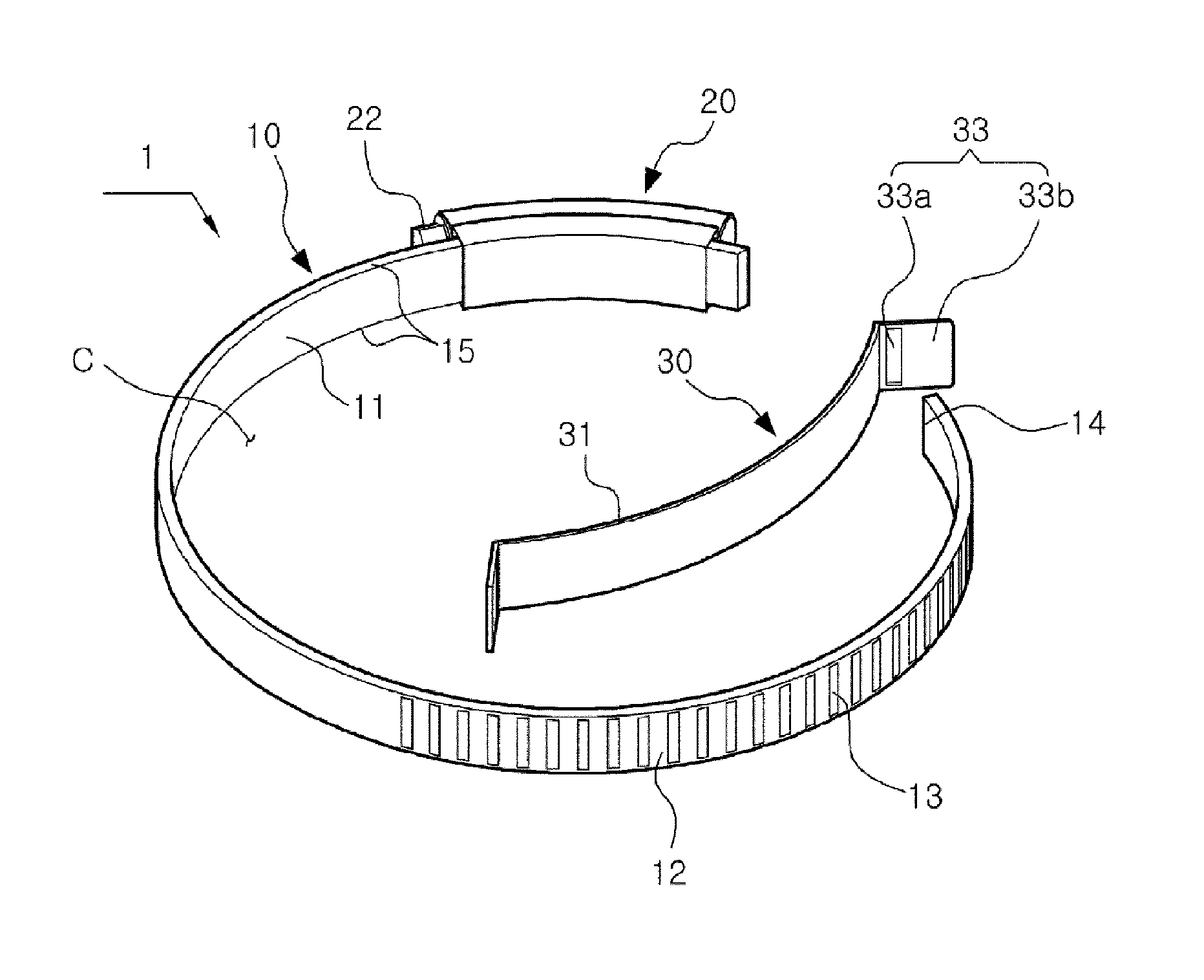
Figure 1 
Figure 2 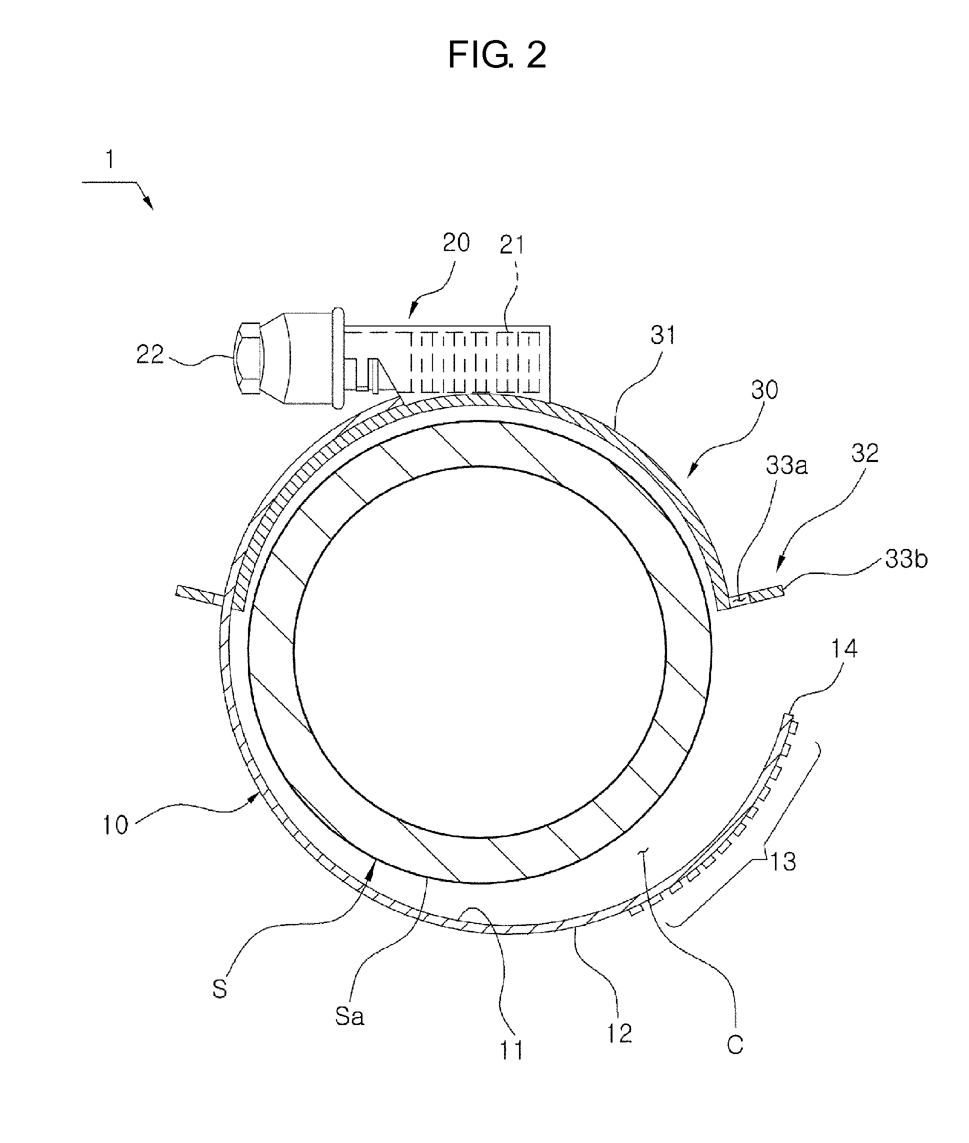
Figure 3
Abstract
Description
TECHNICAL FIELD
[0001] The present invention relates, in general, to a hose fastening clamp which is used to hold hoses that are connected by various pipe connectors in such a way as to be butted to each other, in addition to maintaining airtightness and, more particularly, to a hose fastening clamp, which prevents an outer covering of a hose that is in contact with a band from being pushed in the rotating direction of the band, and increases a clamping force using the band fastened to the hose.BACKGROUND ART
[0002] Hoses which have been used in a variety of fields are manufactured to have various shapes with various materials according to the quality of the material, the thermal treatment method, the purpose of use, and the place of installation. Since the hoses are inexpensive and convenient to install, the use of hoses is gradually increasing.
[0003] The hose is bent or curved according to the place where it is to be installed, and is butted to an adjacent hose. A fastening clamp is pr...
Examples
Example
DESCRIPTION OF REFERENCE CHARACTERS OF IMPORTANT PARTS
[0034]1: clamp S: hose Sa: outer covering[0035]Sp: overlapping portion J: clamping direction[0036]C: open ring[0037]10: band 11: inner surface 12: outer surface[0038]13: fastening screw unit 14: end 15: right and left edges[0039]20: fastening screw 21: corresponding threads 22: screwhead[0040]30: clamping member 31: body 32: coupling unit[0041]33: first coupling unit[0042]33a: insertion hole 33b: locking part[0043]34: second coupling unit 35: slotted part 35a: slot
BEST MODE
[0044]Hereinafter, the hose fastening clamp according to the preferred embodiment of the present invention will be described with reference to the accompanying drawings.
[0045]When describing the hose fastening clamp according to the present invention, the reference of direction will be specified with reference to FIG. 1.
[0046]In the state in which a band is inserted into a fastening screw and thus an open ring is formed in a predetermined size, a threaded side...