

Organizer for releasably accommodating components of blood tube sets, and methods for manufacturing and preparing it
Patent Information
- Authority / Receiving Office
- US · United States
- Current Assignee / Owner
- Publication Date
- 2011-06-16
Smart Images
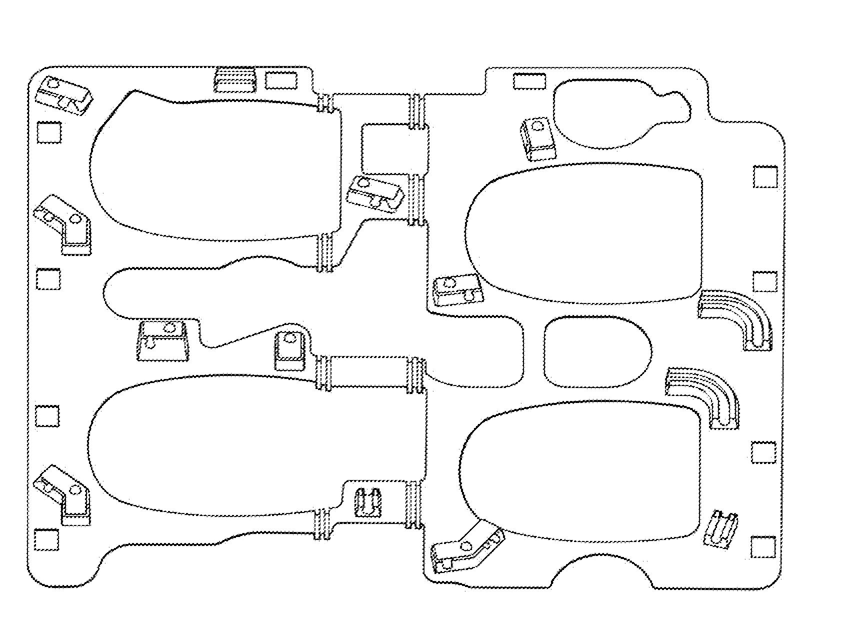
Figure 1 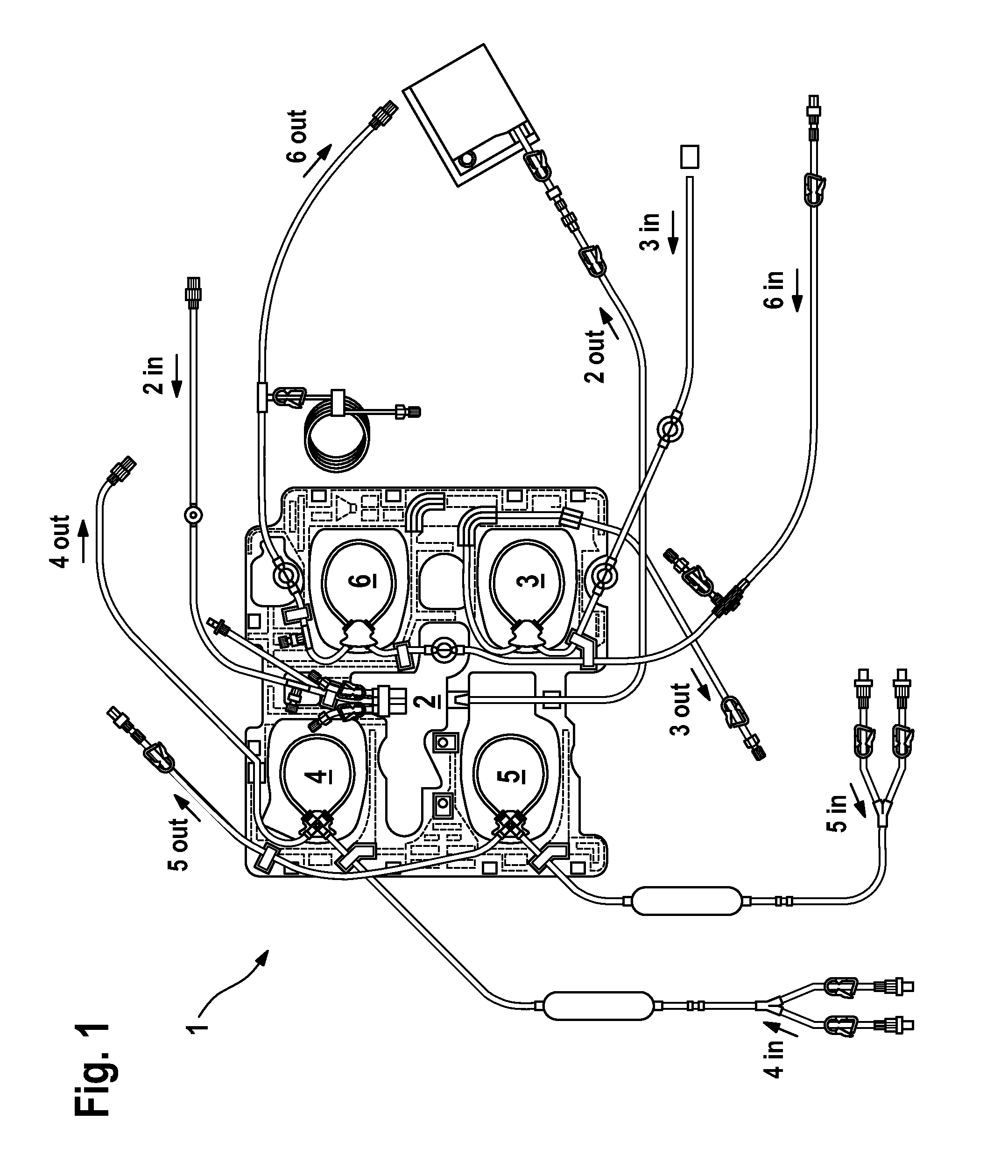
Figure 2 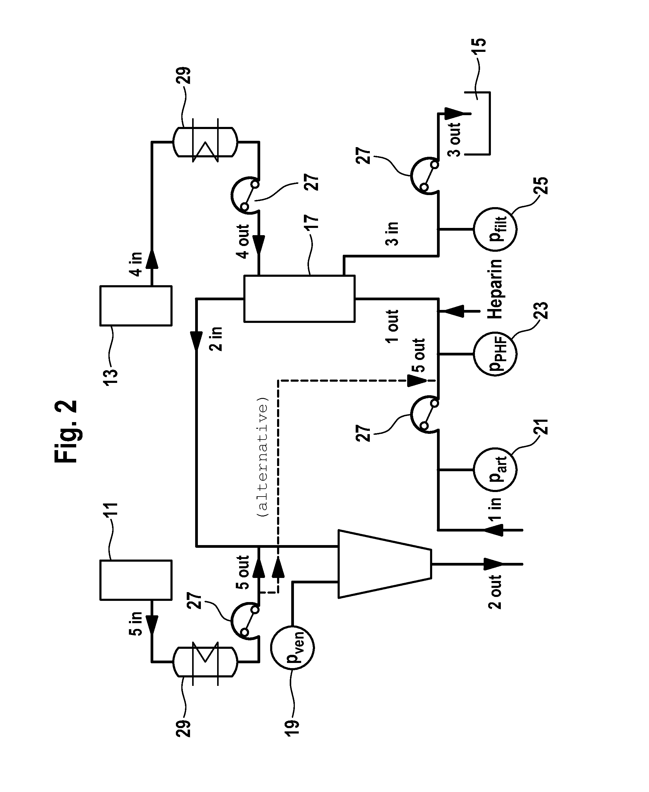
Figure 3
Abstract
Description
FIELD OF INVENTIONThe present invention relates to an organizer. It furthermore relates to a method for manufacturing an organizer and a method for preparing the organizer.BACKGROUND OF THE INVENTIONFrom practice, apparatus for the extracorporeal blood treatment, in particular for a dialysis treatment, are known which allow to selectively carry out different treatment methods or treatment options. For different treatment options, respective different volumes of blood tube sets (disposables) and associated components such as, e.g., tube connections and the like are necessary.In the prior art, compositions of components for the formation of blood tubes are known from which blood tubes or treatment sets for different treatment options may be composed. Such compositions as the one known from EP 1 159 977 B1, for example, may be prepared on so-called “organizers” or “trays” in an orderly manner and in a manner suited for the coupling options furnished by the blood treatment apparatus bei...
Examples
Example
FIG. 7 shows a first embodiment of a fastening means 31 having a receiving portion 33 for releasably accommodating one portion of a blood tube 35, with the receiving portion 33 comprising inclined surfaces 37 for a simplified reception of the tube section 35 in the receiving portion 33. FIG. 7 furthermore shows a tab 39 that is affixed to the fastening means 31 by means of a fixation means 41. As is discernible in FIG. 8, the tab 39 is configured to be elastic and may be raised or bent up elastically for removing the tube 35 in accordance with the representation in FIG. 9. By virtue of its predetermined elasticity, it prevents an inadvertent release of the tube 35 from the receiving portion 33.
The fixation means 41 of the embodiments for fastening the tab of FIGS. 7 through 9 preferably is a weld spot. In this case, the tab is connected to the fastening means while being secured against rotation. It is, however, also possible give to the fixation means 41a rotatable configuration, f...
Example
FIG. 11 shows a fastening means 71 in a second embodiment. The fastening means 71 comprises two tabs 73 and 75 each closing a respective receiving portion 77 and 79 in the same manner as was described by referring to FIGS. 7 through 10.
FIG. 12 shows a fastening means 81 which comprises two tabs 83 and 85 for closing three receiving portions 87, 89, and 91. In each embodiment, the receiving portions may have respective same or different geometrical extensions.
Example
FIG. 13 shows a fastening means 93 according to the invention according to a fourth embodiment in a perspective view. The fastening means 93 is designed or embodied as a clip. The fastening means 93 comprises two legs 95a and 95b, the legs 95a and 95b each laterally confining one channel 97 (in FIG. 13) which is open to the top and to its front and back sides. The channel 97 thus being designed or embodied partly open or half-open serves for accommodating or hosting a tube segment not shown in FIG. 13.
The legs 95a and 95b each have a protrusion or reinforcement, respectively, 99a and 99b, respectively, showing into the direction of the top opening having the width Q of the channel 97. By means of the reinforcements 99a and 99b, a clamping effect on a tube segment (not shown) inserted into the fastening means 93 may be achieved. It is also possible to provide the protrusions or reinforcements along the channel 97 by turns or alternately (“staggered” or “offset”) on or at the one side...