
Forming a 3D structural element
a technology of structural elements and 3d printing, which is applied in the direction of electrographic process, electrographic process apparatus, instruments, etc., can solve the problems of limiting the freedom of the box designer the relative strength configuration cannot be provided by conventional methods of making corrugated boards, and the box designer's freedom to adjust the mechanical characteristics of the box, etc., to achieve control of tensile strength and bending moment, less expensive, and controllable the effect of tensil
Patent Information
- Authority / Receiving Office
- US · United States
- Patent Type
- Applications(United States)
- Current Assignee / Owner
- Publication Date
- 2013-11-07
- Estimated Expiration
- Not applicable · inactive patent
Smart Images
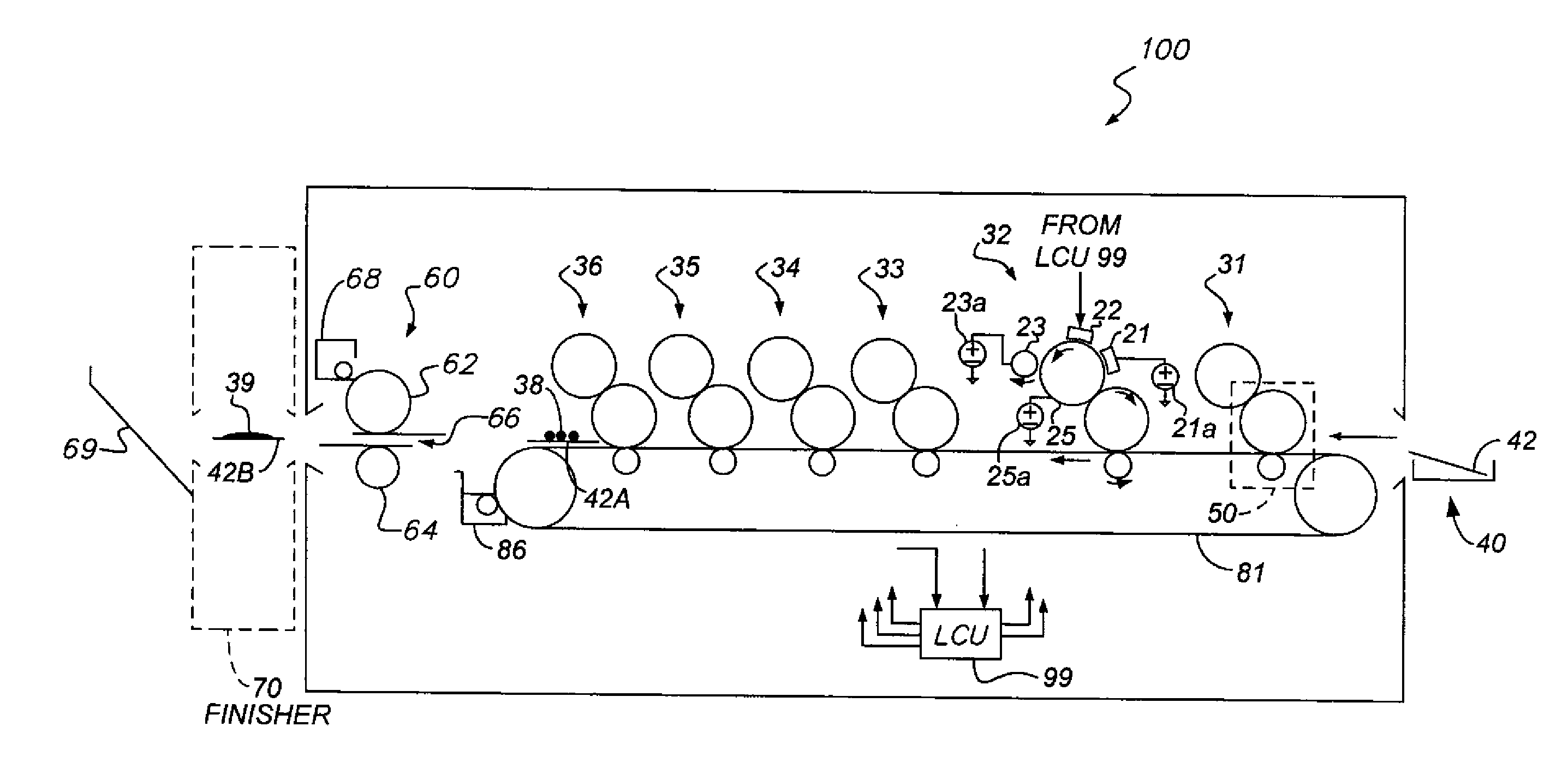
Figure 1 
Figure 2 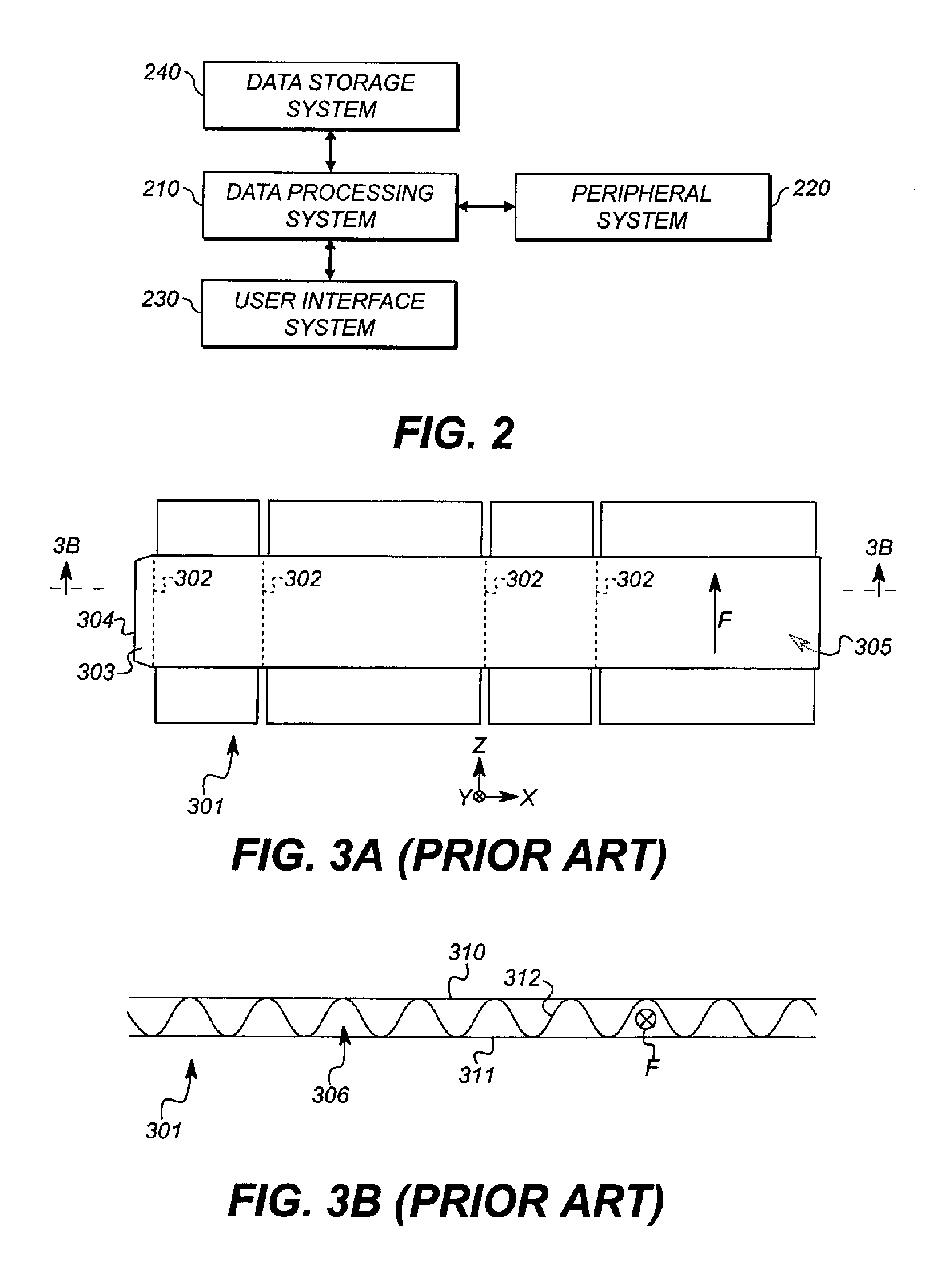
Figure 3
Abstract
Description
CROSS-REFERENCE TO RELATED APPLICATIONS
[0001] This application claims priority of provisional Patent Application No. 61 / 640,929, filed May 1, 2012.
[0002] This application is co-filed with and has related subject matter to U.S. Patent Application No. 61 / 640,914, filed May 1, 2012, titled “FORMING A STRUCTURAL LAMINATE,” and U.S. Patent Application No. 61 / 540,909, filed May 1, 2012, titled “FORMING A STRUCTURAL LAMINATE,” each of which is incorporated herein by reference in its entirety.FIELD OF THE INVENTION
[0003] This invention pertains to the field of printed manufacturing and more particularly to printing structural elements.BACKGROUND OF THE INVENTION
[0004] Corrugated cardboard or fiberboard is widely used to package goods for transit. An outer sheet of liner (or “linerboard”) is glued to a fluted sheet to provide stiffness in the direction in which the flutes extend. A second outer sheet of liner can be glued to the fluted sheet opposite the first outer sheet to provide stiffness in...
Examples
Embodiment Construction
[0055]As used herein, the terms “receiver,”“receivers,”“medium,”“media,”“recording medium,” and “recording media” are used interchangeably. “Sheet” and “web” receivers are used interchangeably except when discussing embodiments that are particularly adapted to use one of those styles of receiver. “Adhere” is used herein both intransitively (toner adheres to paper) and transitively (toner adheres two sheets to each other, i.e., the adhesive forces between a toner mass and each of two sheets holds those two sheets together).
[0056]Referring back to FIG. 3B, the direction F of extension of flutes 306 is the direction in which a ray extended in direction F will not cross fluted sheet 312, even if extended to the edge of box blank 301. In conventional corrugated board, such as that shown here, the opposite to direction F can also be considered the direction of extension of flutes 306, since either direction F or its opposite can be extended to the edges of box blank 301 without crossing f...