
Dc-dc converter, secondary battery charge and discharge system, and method of controlling dc-dc converter
a converter and secondary battery technology, applied in the direction of electric variable regulation, process and machine control, instruments, etc., can solve the problems of increasing cost and consuming energy of snubber resistors
Patent Information
- Authority / Receiving Office
- US · United States
- Patent Type
- Applications(United States)
- Current Assignee / Owner
- Publication Date
- 2015-07-30
Smart Images
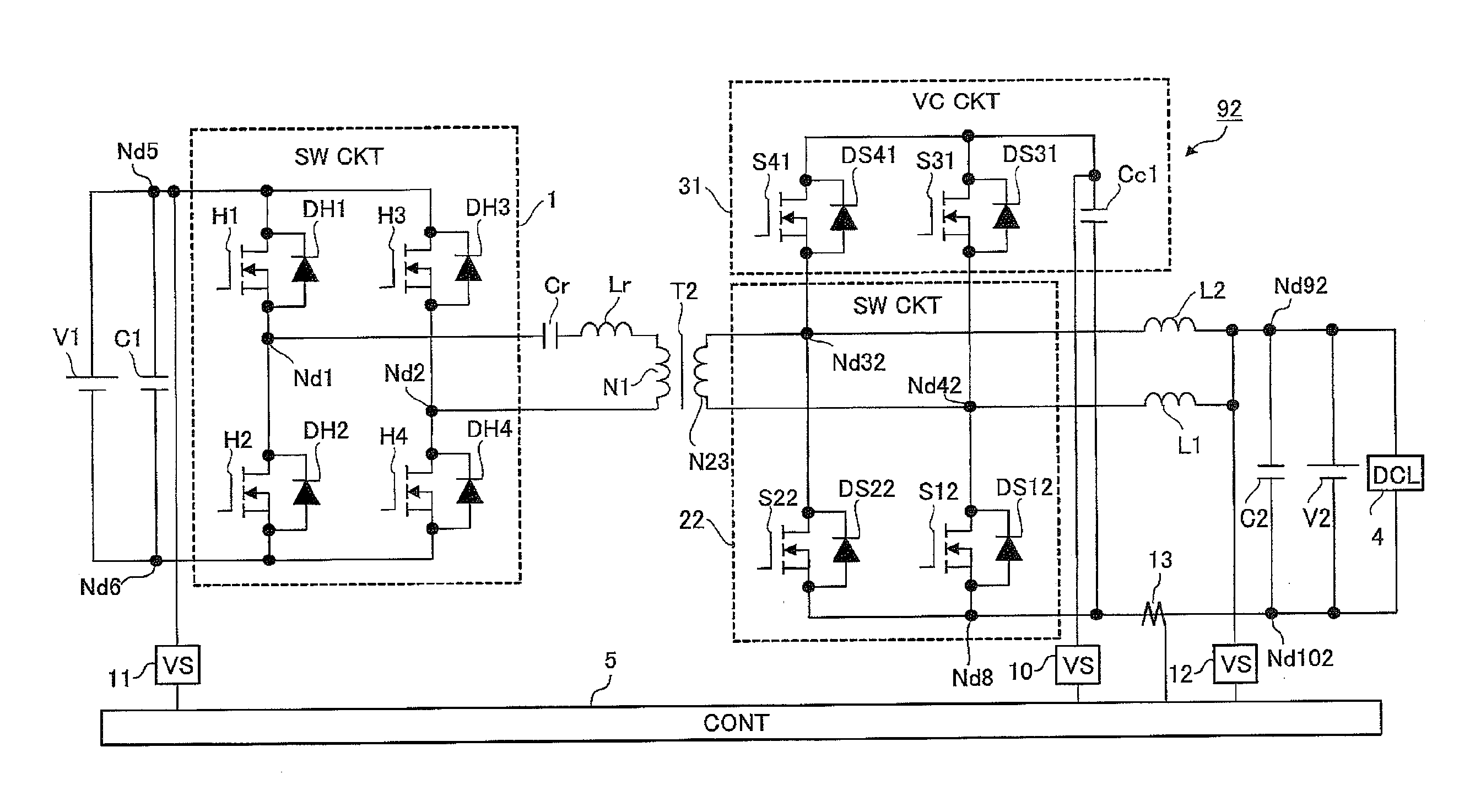
Figure 1 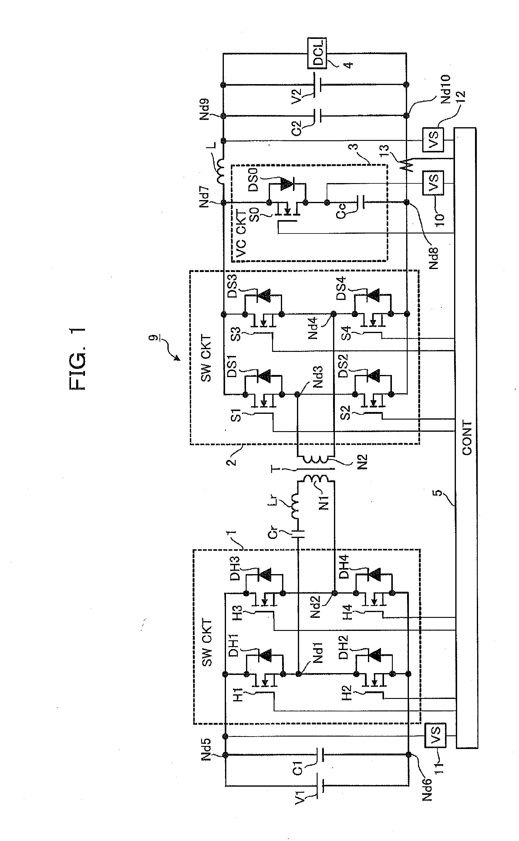
Figure 2 
Figure 3
Abstract
Description
CROSS REFERENCE TO RELATED APPLICATION
[0001] This application claims the foreign priority benefit under Title 35, United States Code, §119(a)-(d) of Japanese Patent Application No. 2014-011776, filed on Jan. 24, 2014 in the Japan Patent Office, the disclosure of which is herein incorporated by reference in its entirety.BACKGROUND OF THE INVENTION
[0002] 1. Field of the Invention
[0003] The present invention relates to a DC-DC Converter for supplying a power of a DC power source to a DC load or a DC power source, and a secondary battery charge and discharge system including the same, and a method of controlling the DC-DC Converter.
[0004] 2. Description of the Related Art
[0005] Recently, systems including a DC power source such as a secondary battery, a solar cell, a fuel cell, etc. have been developed due to increase demands for global environment conservation. These systems require a DC-DC converter for supplying a power from a DC power source to a load, or another DC power source.
[0006] An...
Examples
first embodiment
[0061]FIG. 1 is a circuit diagram of a DC-DC converting system 109 including a DC-DC converter 9 according to a first embodiment of the present invention.
[0062]As shown in FIG. 1, a DC-DC converter 9 includes switching circuits 1, 2, a voltage clamp circuit 3, and a controller 5 for controlling ON-OFF states of respective switching devices included in these circuits. The DC-DC converter 9 is connected between a DC power source V1 (first DC power source) and a DC power source V2 (second DC power source) connected to a DC load 4. The DC-DC converter 9 is a device for supplying a power from the DC power source V1 to the DC load4 or the DC power source V2 and a power from the DC power source V2 to the DC power source V1.
[0063]Connected between nodes Nd5, Nd6 which are DC terminals of the switching circuit 1 is a smoothing capacitor C1 (first smoothing capacitor).
[0064]Connected between nodes Nd1, Nd2, which are AC terminals of the switching circuit 1 (first switching circuit), are a res...
second embodiment
[0168]FIG. 25 is a schematic circuit diagram of a DC-DC converting system 191 including the DC-DC converter 91 according to a second embodiment.
[0169]As shown shown in FIG. 25, a DC-DC converter 91 according to the second embodiment includes the switching circuit 1 which is similar to the switching circuit in the DC-DC converter 9 (see FIG. 1), a switching circuit 21 different from that in the first embodiment, a voltage clamp circuit 31, and the controller 5 for controlling states of respective switching devices included in these circuits between ON and OFF. The DC-DC converter 91 according to the second embodiment is connected between the DC power source V1 and the DC power source V2 connected to the DC load 4 like the first embodiment. The DC-DC converter 91 supplies a power from the DC power source V1 to the DC load 4 and the DC power source V2 and a power from the DC power source V2 to the DC power source V1.
[0170]The switching circuit 1 has a structure which is similar to that...
third embodiment
[0179]FIG. 26 is a circuit diagram of a DC-DC converting system 192 including a DC-DC converter 92 according to the present invention. As shown in FIG. 26, the DC-DC converter 92 according to the third embodiment includes the switching circuit 1, which is similar to the DC-DC converter 9 and a switching circuit 22, which are different from the switching circuit of the first embodiment, the voltage clamp circuit 31, and the controller 5 for controlling ON-OFF states of respective switching devices included in these circuits. The DC-DC converter 92 according to the third embodiment is connected between the DC power source V1 and the DC power source V2 connected to the DC load 4. The DC-DC converter 92 is a device for supplying a power from the DC power source V1 to the DC load 4 or the DC power source V2 and a power from the DC power source V2 to the DC power source V1.
[0180]The switching circuit 1 is configured similarly to the first embodiment.
[0181]The switching circuit 22 is conne...