
Air valve connecting device having pivotal actuating knob
a technology of pivotal actuating knob and connecting device, which is applied in the direction of machines/engines, couplings, positive displacement liquid engines, etc., can solve the problems of difficult operation or ineffective grasping of the structure, and achieve the effect of easy operation, convenient connection, and convenient actuation or operation
Patent Information
- Authority / Receiving Office
- US · United States
- Patent Type
- Applications(United States)
- Current Assignee / Owner
- Publication Date
- 2018-01-11
Smart Images
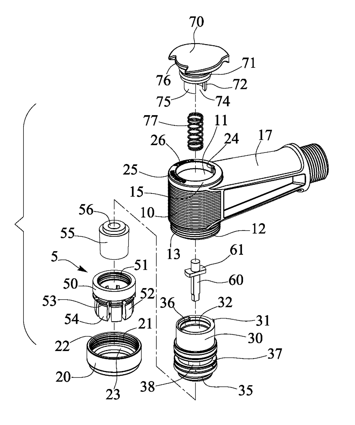
Figure 1 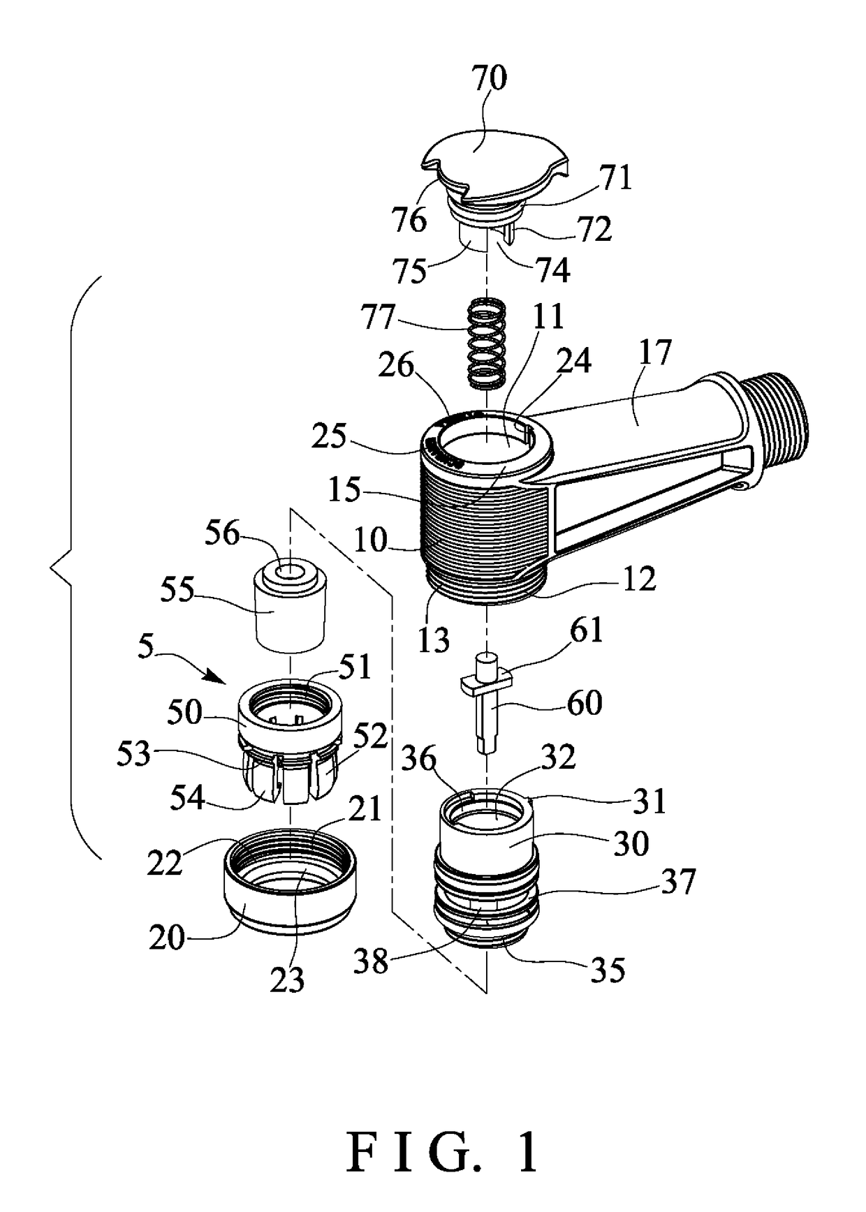
Figure 2 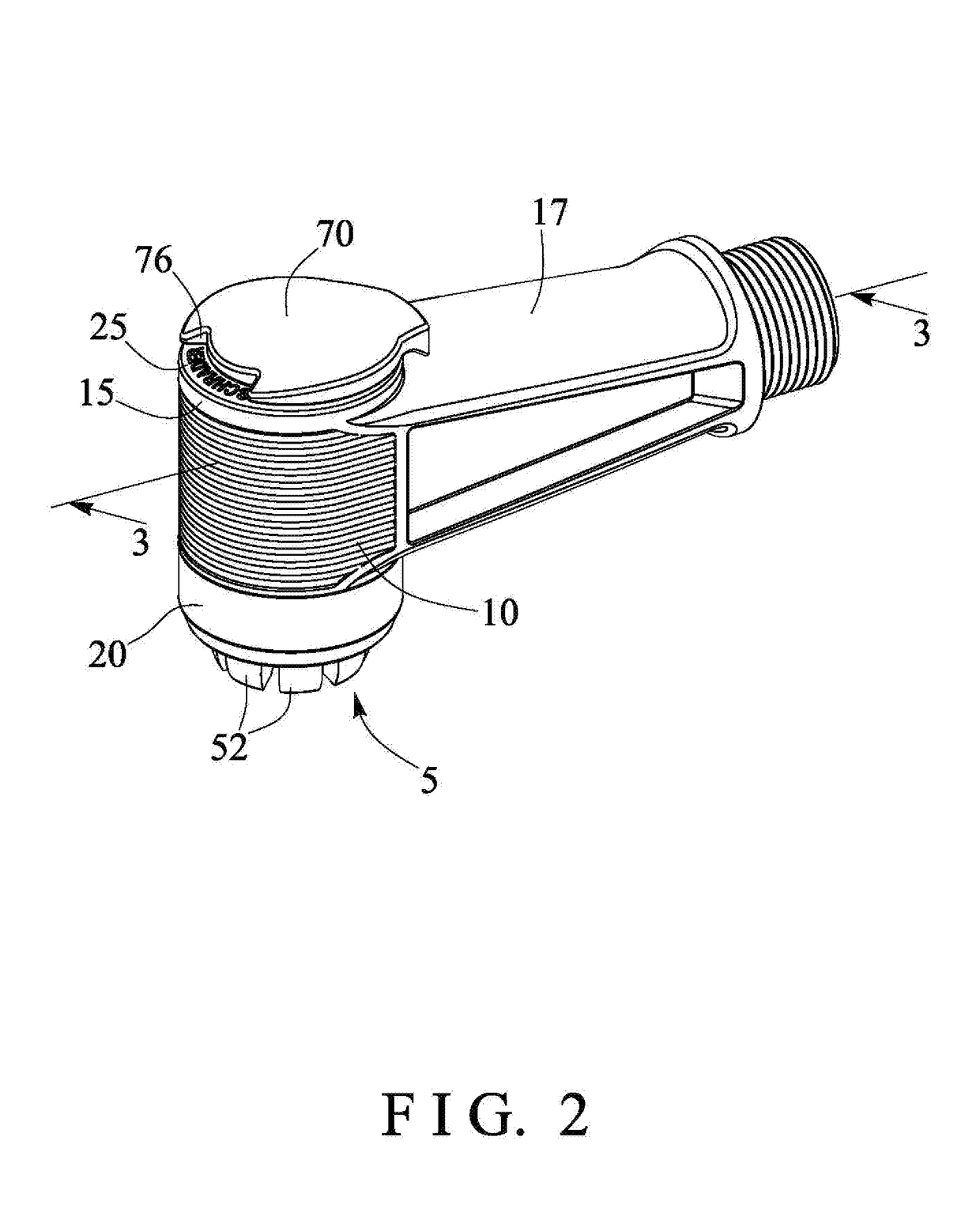
Figure 3
Abstract
Description
BACKGROUND OF THE INVENTION1. Field of the Invention
[0001] The present invention relates to an air valve connecting head or device, and more particularly to an air valve connecting device including a simplified or improved structure for easily connecting to various inflation valves and for being easily actuated or operated with a single hand of the user and for being easily manufactured with a decreased manufacturing cost.2. Description of the Prior Art
[0002] Typical air valve connecting devices comprise a valve housing including one end for connecting or coupling to a pressurized air reservoir and for receiving the pressurized air from the pressurized air reservoir, and a fitting port formed in the other end of the valve housing for receiving or engaging with an inflation valve and for inflating the balls, the inner tires of the bicycles or the motorcycles or the vehicles, the present inventor has developed various kinds of air valve connecting devices.
[0003] For example, U.S. Pat. No...
Examples
Embodiment Construction
[0021]Referring to the drawings, and initially to FIGS. 1-3, an air valve connecting device in accordance with the present invention comprises a head body or housing 10 including a chamber 11 formed therein, and including an outer thread 12 formed in the one or first or lower end portion 13 thereof, and including a peripheral flange 14 extended radially and inwardly into the chamber 11 of the housing 10 at the other or second or upper end portion 15 of the housing 10 for forming or defining an inner peripheral shoulder 16 in the second end portion 15 of the housing 10, and including a cylindrical tube 17 laterally extended from the housing 10 and substantially perpendicular to the housing 10, and including a bore 18 formed in the cylindrical tube 17 for coupling to an air pump (not illustrated), a pressurized air reservoir or the like, and including a passage 19 formed therein and communicating with the chamber 11 of the housing 10 and the bore 18 of the cylindrical tube 17.
[0022]Th...