
Golf ball marker having clip part
Patent Information
- Authority / Receiving Office
- US · United States
- Current Assignee / Owner
- Publication Date
- 2019-08-29
Smart Images
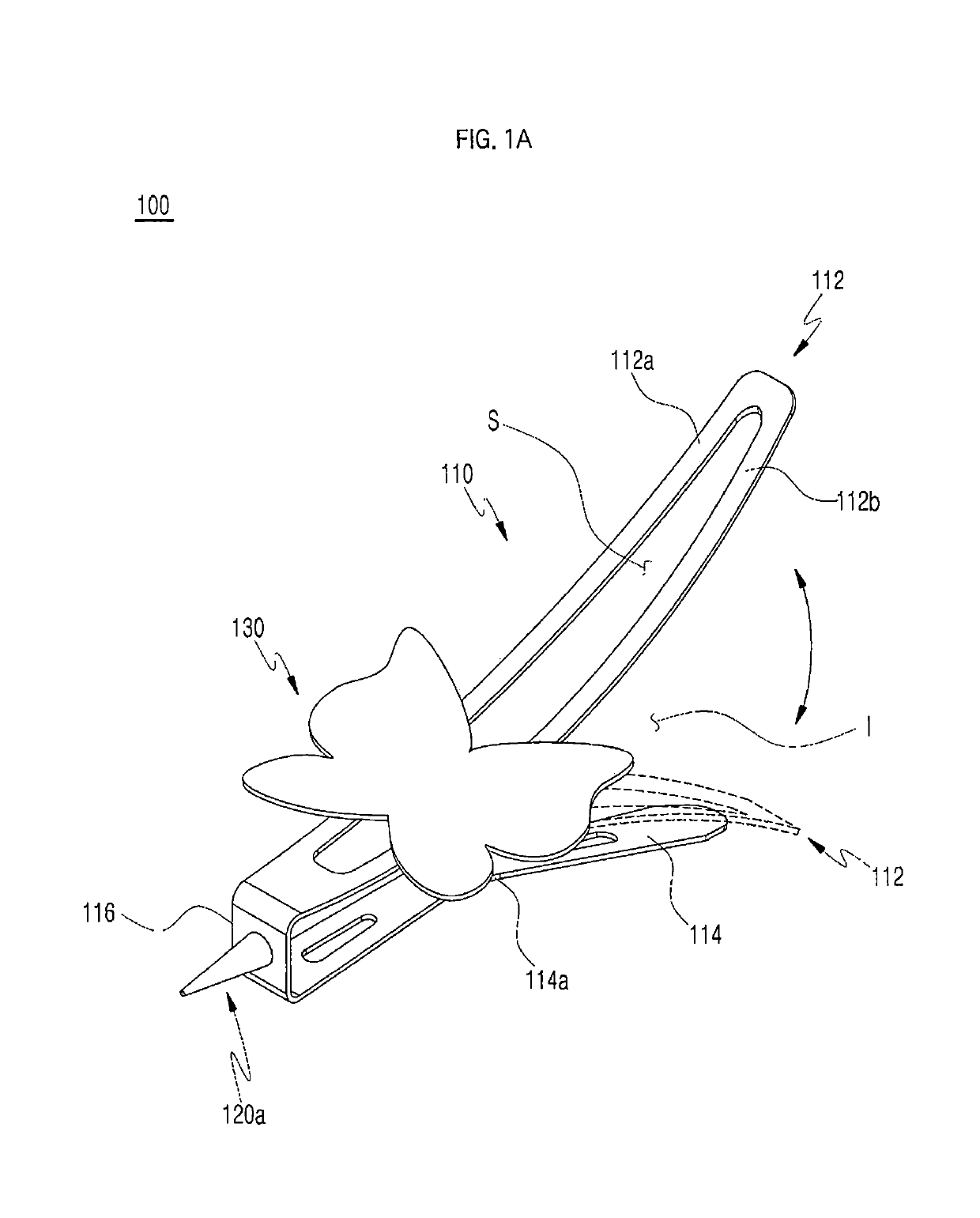
Figure 1 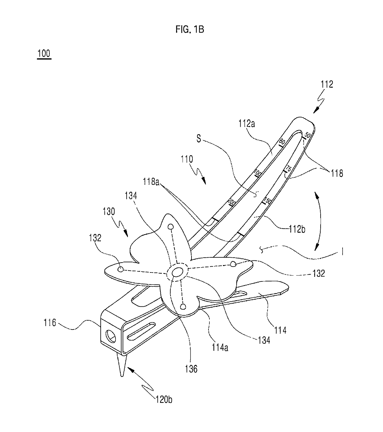
Figure 2 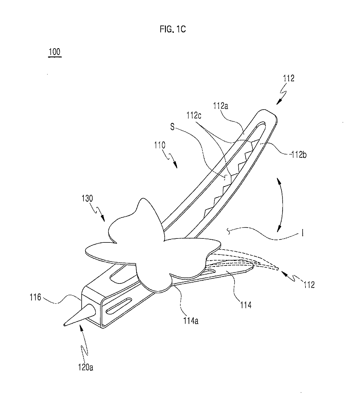
Figure 3
Abstract
Description
TECHNICAL FIELD
[0001] The present disclosure relates to a golf ball marker having a clip part, and more particularly, to a golf ball marker, which is configured in a clip shape to be capable of being selectively attached to / detached from a pocket, a belt, a visor, or head, and which is capable of indicating the position of a golf ball upon being fixed to the ground of a golf course.BACKGROUND ART
[0002] When enjoying golf at a field golf course, players hit a golf ball from a tee box or fairway to land upon a green with a hole cup. When several players play on the green landed thereby, each golf player indicates the position of his / her golf ball to be putted by placing a golf ball marker at the green position where the golf ball has been landed such that the golf ball normally does not interfere with the other players' putting.
[0003] Such golf ball markers are generally manufactured in the form of coins, but there is a problem in that the golf ball markers may not be easily recognized o...
Examples
first embodiment
[0026]FIG. 1A is a perspective view of a golf ball marker having a clip part according to the present disclosure;
[0027]FIG. 1B is a perspective view of a first modification of the golf ball marker of FIG. 1A;
[0028]FIG. 1C is a perspective view of a second modification of the golf ball marker of FIG. 1A;
[0029]FIG. 2A illustrates states in which the golf ball marker of FIG. 1A is worn;
[0030]FIG. 2B is a view illustrating the state in which the golf ball marker of FIG. 1A is installed and fixed in the vertical direction with respect to a green;
second embodiment
[0031]FIG. 3A is a perspective view of a golf ball marker having a clip part according to the present disclosure;
[0032]FIG. 3B is a perspective view of a first modification of the golf ball marker of FIG. 3A;
[0033]FIG. 3C is a perspective view of a second modification of the golf ball marker of FIG. 3A;
[0034]FIG. 3D is a perspective view of a third modification of the golf ball marker of FIG. 3A;
[0035]FIG. 4 is a view illustrating the state in which the golf ball marker of FIG. 3A is used in a green;
[0036]FIG. 5 is a view illustrating the state in which a distance to a hole cup is roughly measured using the golf ball marker of FIG. 3B;
[0037]FIG. 6 is a view illustrating the state in which the golf ball marker of FIG. 3C is used in a green; and
[0038]FIG. 7 is a view illustrating the state in which the golf ball marker of FIG. 3D is used in a green.
DESCRIPTIONS OF REFERENCE NUMERALS OF DRAWINGS
[0039]10: hole cup, 11: hole cup flag,
[0040]100: golf ball marker having a clip part accordi...