
Turbocharger having a thermal dam
a technology of thermal dam and turbine, which is applied in the direction of sliding contact bearings, mechanical equipment, machines/engines, etc., can solve the problems of increased vehicle emissions, increased heat transfer, and failure of turbines, so as to reduce heat transfer, reduce heat transfer, and increase compressor performance
Patent Information
- Authority / Receiving Office
- US · United States
- Patent Type
- Applications(United States)
- Current Assignee / Owner
- Publication Date
- 2021-10-21
Smart Images
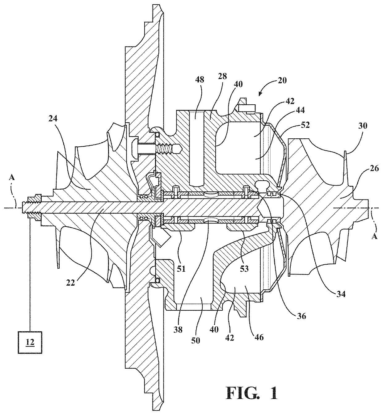
Figure 1 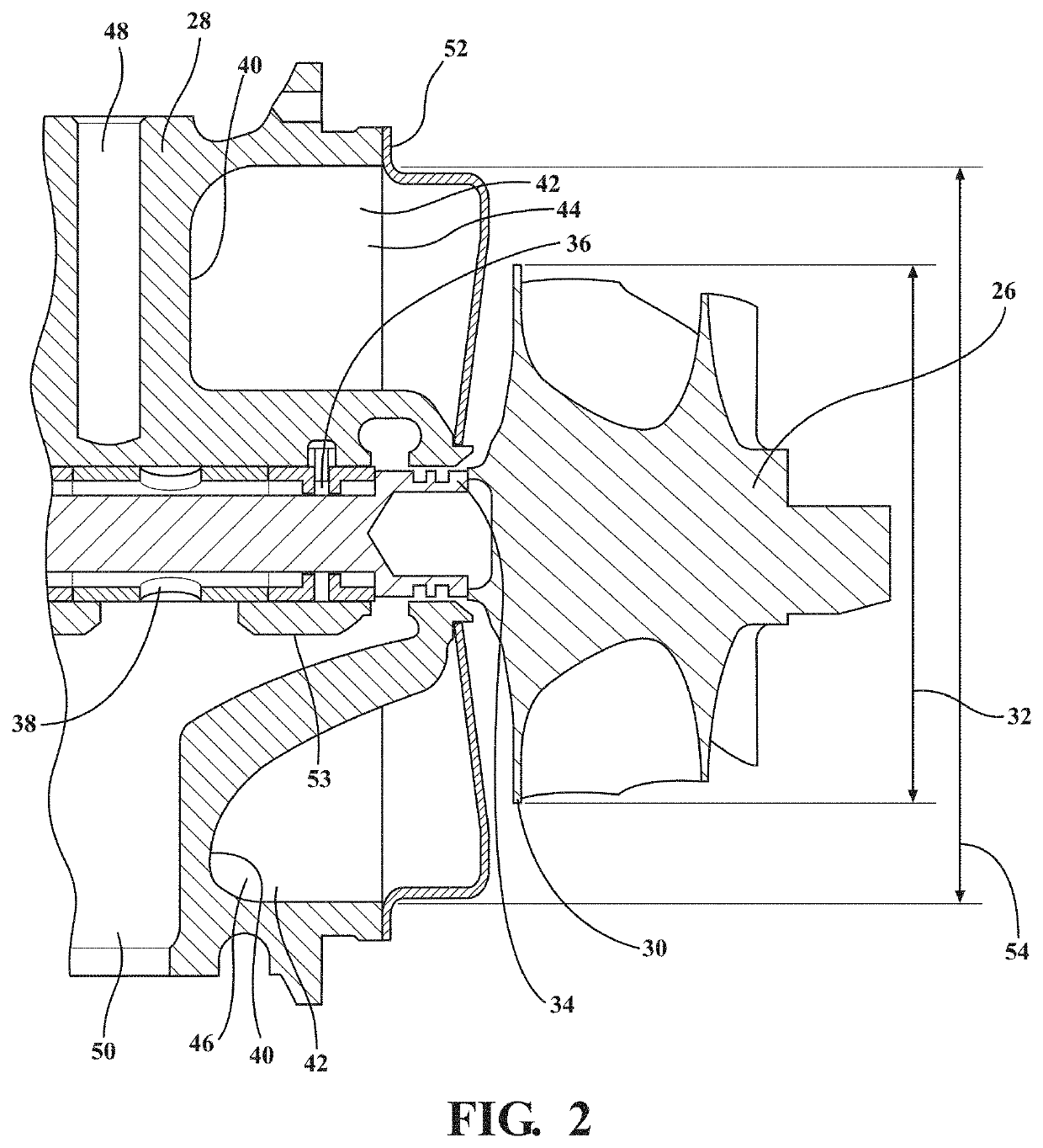
Figure 2 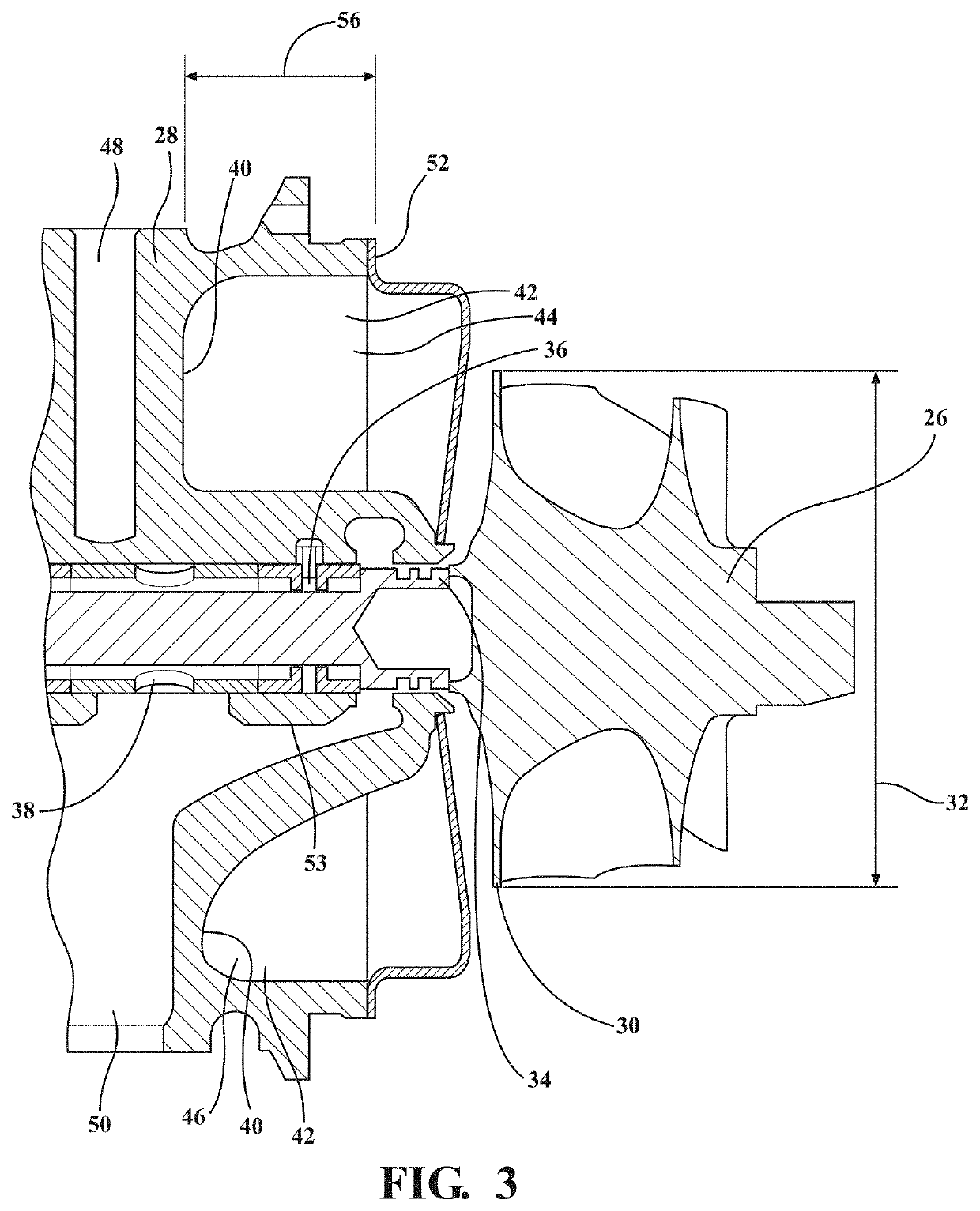
Figure 3
Abstract
Description
BACKGROUND OF THE INVENTION1. Field of the Invention
[0001] The present invention generally relates to a turbocharger and more particularly to a turbocharger having a thermal dam.2. Description of the Related Art
[0002] Turbochargers include a turbine wheel, a compressor wheel coupled to the turbine wheel through a shaft, and a bearing housing extending about the shaft and disposed between the turbine wheel and the compressor wheel. Turbochargers use exhaust flow from an internal combustion engine and deliver compressed air to the internal combustion engine. More specifically, turbochargers use exhaust flow to spin the turbine wheel. The turbine wheel, in turn, rotates the shaft which rotates the compressor wheel to deliver the compressed air the internal combustion engine. However, the exhaust flow used to spin the turbine wheel is very hot which in turn leads to components of the bearing housing adjacent to the turbine wheel also getting hot, which can cause turbocharger failure.[0003...
Examples
Embodiment Construction
[0015]With reference to the Figures, wherein like numerals indicate like parts throughout the several views, a turbocharger 20 is generally shown in FIG. 1. The turbocharger 20 is coupled to a vehicle engine 12 such as an internal combustion engine 12, however, it is contemplated that the vehicle engine may be any type of power generator including but not limited to an electric motor, a battery, or a fuel cell. The turbocharger 20 receives exhaust gas from the internal combustion engine 12 and delivers compressed air to the internal combustion engine 12.
[0016]Although not required, the turbocharger 20 is typically used in passenger and commercial automotive applications. However, it is to be appreciated that the turbocharger 20 may be used in non-automotive applications such as heavy equipment applications, non-automotive diesel engine applications, non-automotive motor applications, and the like.
[0017]With reference again to FIG. 1, the turbocharger 20 typically includes a turbocha...