
Power module with built-in drive circuits
a power module and drive circuit technology, applied in pulse manipulation, pulse technique, instruments, etc., can solve the problems of low collector current area, difficult to ensure the desired dead time margin, and turn-off surge voltage,
Patent Information
- Authority / Receiving Office
- US · United States
- Current Assignee / Owner
- Publication Date
- 2021-11-18
Smart Images
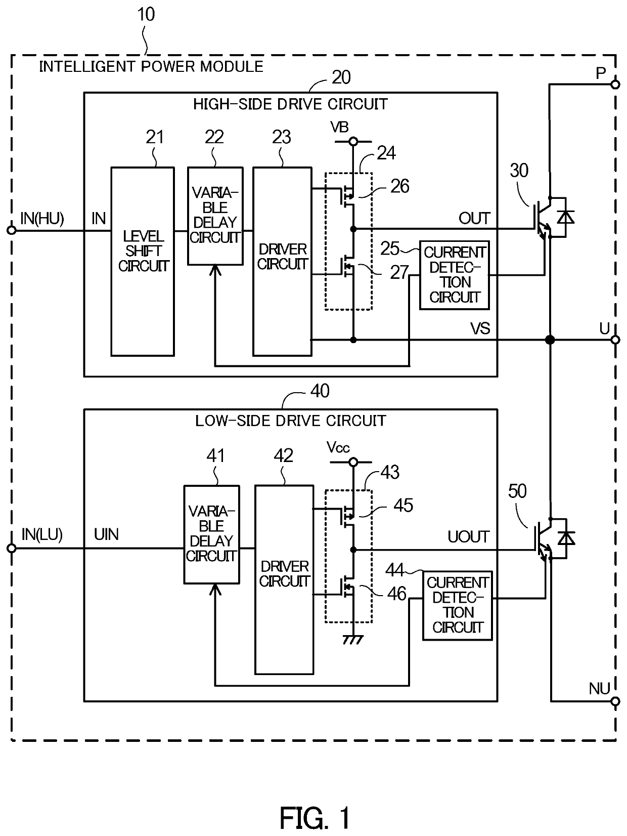
Figure 1 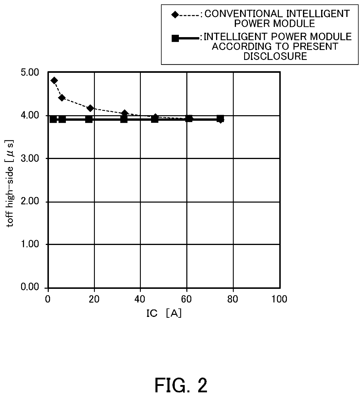
Figure 2 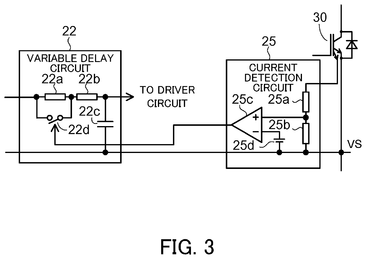
Figure 3
Abstract
Description
CROSS-REFERENCE TO RELATED APPLICATION
[0001] This application is based upon and claims the benefit of priority of the prior Japanese Patent Application No. 2020-084784, filed on May 13, 2020, the entire contents of which are incorporated herein by reference.BACKGROUND OF THE INVENTION1. Field of the Invention
[0002] The embodiments discussed herein relate to a power module with built-in drive circuits.2. Background of the Related Art
[0003] Intelligent power modules are used in motor drive inverters. Some intelligent power modules include a plurality of combinations of a half bridge circuit made up of two switching elements connected in series and a drive circuit which on-off drives the switching elements.
[0004] FIG. 7 is a circuit diagram illustrative of an example of the structure of the whole of an intelligent power module used in a three-phase motor drive inverter. FIG. 8 is a circuit diagram illustrative of an example of the structure of a circuit corresponding to one phase of the in...
Examples
first embodiment
[0040]FIG. 1 is a circuit diagram illustrative of an example of the structure of an intelligent power module according to a FIG. 2 illustrates the current-dependent characteristic of a high-side turn-off time. FIG. 3 is a circuit diagram illustrative of main components on the high side. FIG. 4 is a circuit diagram illustrative of main components on the low side.
[0041]An intelligent power module 10 according to a first embodiment includes a high-side drive circuit 20, a switching element 30, a low-side drive circuit 40, and a switching element 50. Each of the switching elements 30 and 50 is an IGBT and a free wheeling diode connected in inverse parallel. An IGBT includes a main IGBT and a sense IGBT which is a current sense element for detecting a current flowing through the main IGBT.
[0042]The high-side drive circuit 20 includes a level shift circuit 21, a variable delay circuit 22, a driver circuit 23, an output circuit 24, and a current detection circuit 25. The output circuit 24...
second embodiment
[0063]As illustrated in FIG. 5, a high-side drive circuit 20 in a second embodiment includes a variable delay circuit 22A and a current detection circuit 25A. The variable delay circuit 22A includes a resistor 22e, two capacitors 22f and 22g, and a switch 22h. An input terminal of the variable delay circuit 22A is connected to one terminal of the resistor 22e. The other terminal of the resistor 22e is connected to one terminal of the capacitor 22f, one terminal of the switch 22h, and an output terminal of the variable delay circuit 22A. The other terminal of the switch 22h is connected to one terminal of the capacitor 22g. The other terminal of the capacitor 22f and the other terminal of the capacitor 22g are connected to a line of a VS terminal which is a reference potential of the high-side drive circuit 20. A control input terminal of the switch 22h is connected to an output terminal of the current detection circuit 25A.
[0064]The current detection circuit 25A includes two resisto...