
Light wavelength meter
a wavelength meter and light technology, applied in the field of light wavelength meter, can solve the problems of complex operation principle, limited measurement resolution of other systems, and difficult to set-up and maintain, and achieve the effect of simple and economical, low cost of wavelength meter, and easy setup and maintenan
Patent Information
- Authority / Receiving Office
- US · United States
- Patent Type
- Patents(United States)
- Current Assignee / Owner
- Publication Date
- 2005-02-22
- Estimated Expiration
- Not applicable · inactive patent
Smart Images
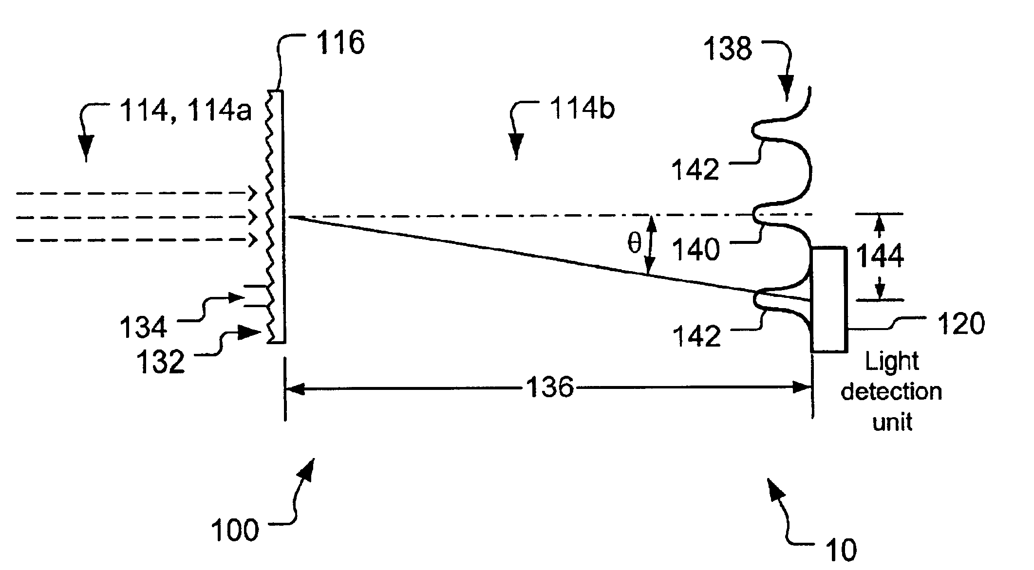
Figure 1 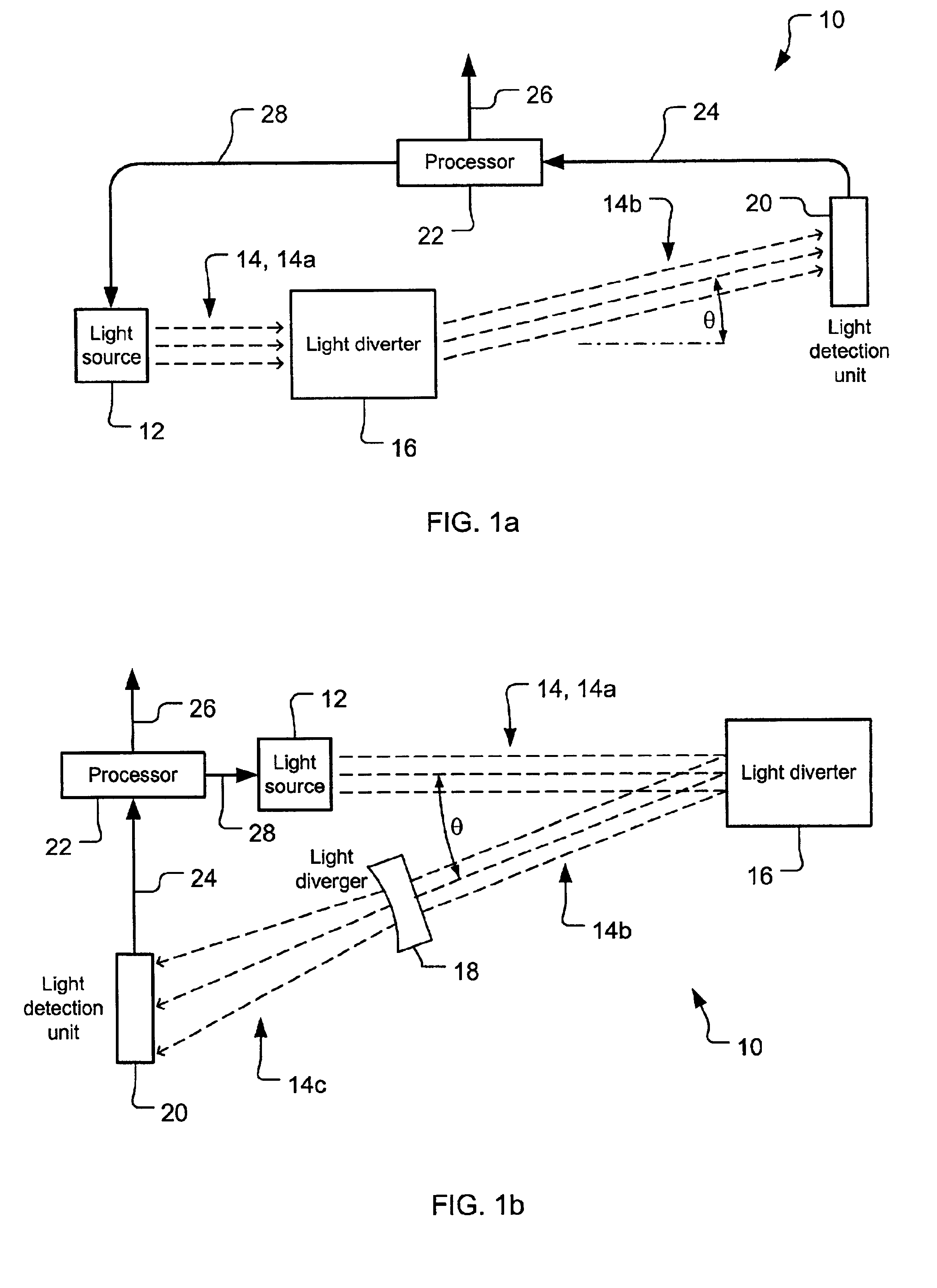
Figure 2 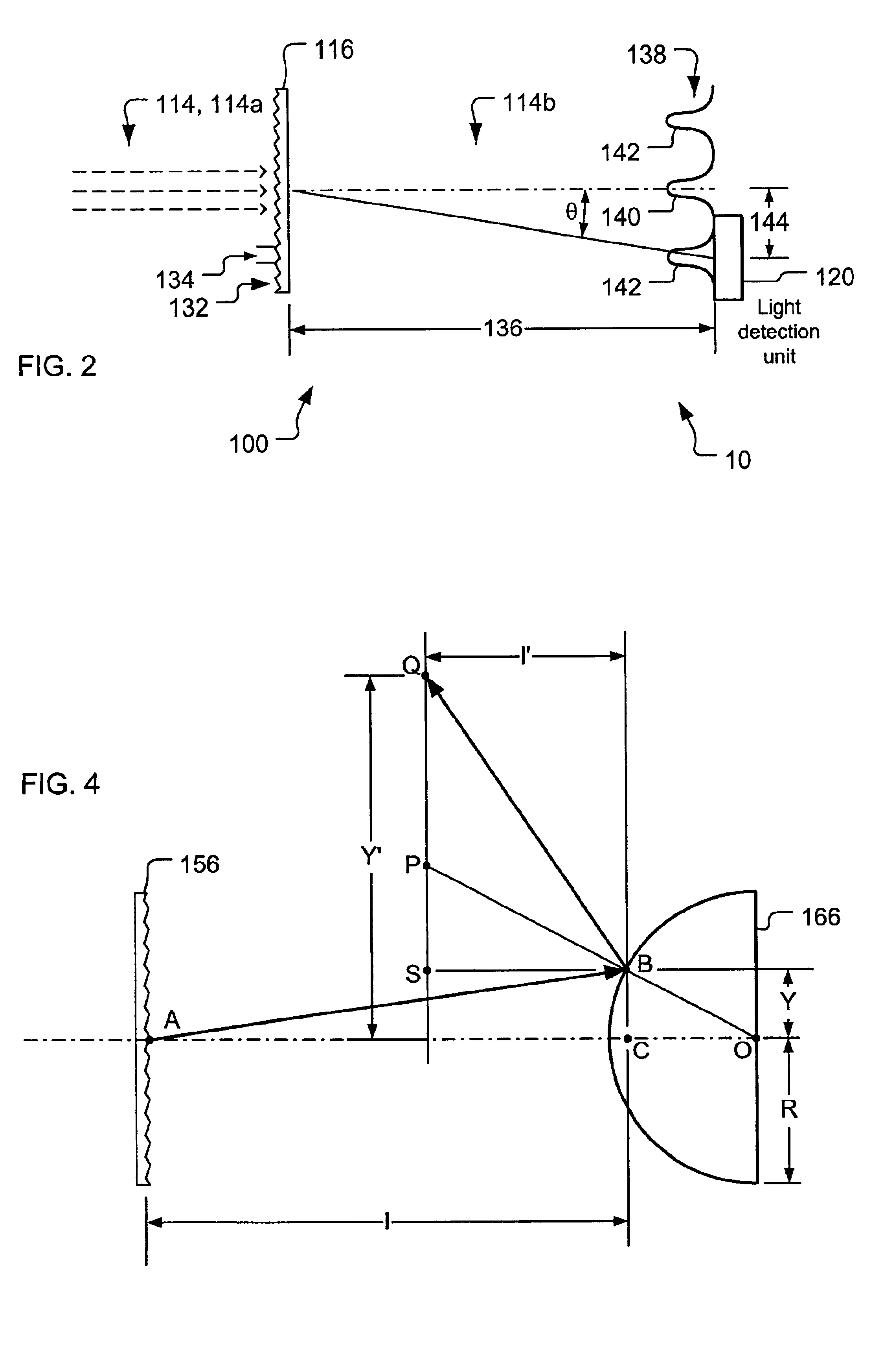
Figure 3
Abstract
Description
TECHNICAL FIELDThe present invention relates generally to methods and apparatus for using, controlling and detecting radiant energy, and more particularly to light wavelength determination. It is anticipated that the present invention will be employed widely in the calibration of light wavelength and the stabilization of light frequency, particularly in the telecommunications industry, but the invention is also well suited for use in laboratory measurement and in many other industries.BACKGROUND ARTThe ability to measure the wavelength or frequency (herein treated as equivalent with both meant when either term is used) of light is highly useful in industry and basic research. The telecommunications industry provides an excellent example, and will be used as the one herein. One brief discussion of the need for this capability in telecommunications can be found in REIZEMAN. “Optical Nets Brace for Even Heavier Traffic,” IEEE Spectrum, Jan. 2001. pg. 44-46. discussing the growth of wav...
Examples
embodiment 300
FIG. 7 is a block diagram presenting a multiple slit embodiment 300 of the inventive wavelength meter 10. A light source (not shown) produces a light beam 314, having a first beam portion 314a and a second beam portion 314b. The first beam portion 314a is received at a slit plate 316 (serving here as a transmissive light diverter) which imparts to the second beam portion 314b a transverse displacement characteristic. The second beam portion 314b is, in turn, received by a diverging lens 318 (used as a light diverger for angular resolution extension here) and produces a third beam portion 314c. A light detection unit 320 then detects aspects of the transverse displacement in the third beam portion 314c and produces a raw signal which is representative thereof. With techniques and components described elsewhere herein, this raw signal can then be appropriately processed to meter the wavelength or lock the frequency in the light beam 314.
Aside from the alternate type of light diverter ...
embodiment 400
FIG. 8 is a block diagram presenting an acousto-optical embodiment 400 of the inventive wavelength meter 10. A light source (not shown) produces a light beam 414, having a first beam portion 414a and a second beam portion 414b. The first beam portion 414a is received at an acousto-optical unit 416 (serving here as a transmissive light diverter) which imparts to the second beam portion 414b a transverse displacement characteristic. A light detection unit 420 then detects aspects of the transverse displacement in the second beam portion 414b and produces a raw signal which is representative thereof. With techniques and components described elsewhere herein, this raw signal can then be appropriately processed to meter the wavelength or lock the frequency in the light beam 414.
The acousto-optical unit 416 includes an acousto-optic crystal, such as LiNbO3, ADP, KDP, etc. In the acousto-optic crystal the light beam 414 is modulated by interaction with sound waves, typically created by a p...