
Liquid dispensing device
a liquid dispensing device and soft drink technology, applied in the direction of liquid dispensing devices, transportation and packaging, packaging, etc., can solve the problems of difficult implementation of additional “add-on” lines after the initial installation of soft drink dispensing machines, increase and prevent the backflow of essence lines. , the effect of affecting the carbonation level of final beverages
Patent Information
- Authority / Receiving Office
- US · United States
- Patent Type
- Patents(United States)
- Current Assignee / Owner
- Publication Date
- 2006-05-23
- Estimated Expiration
- Not applicable · inactive patent
Smart Images
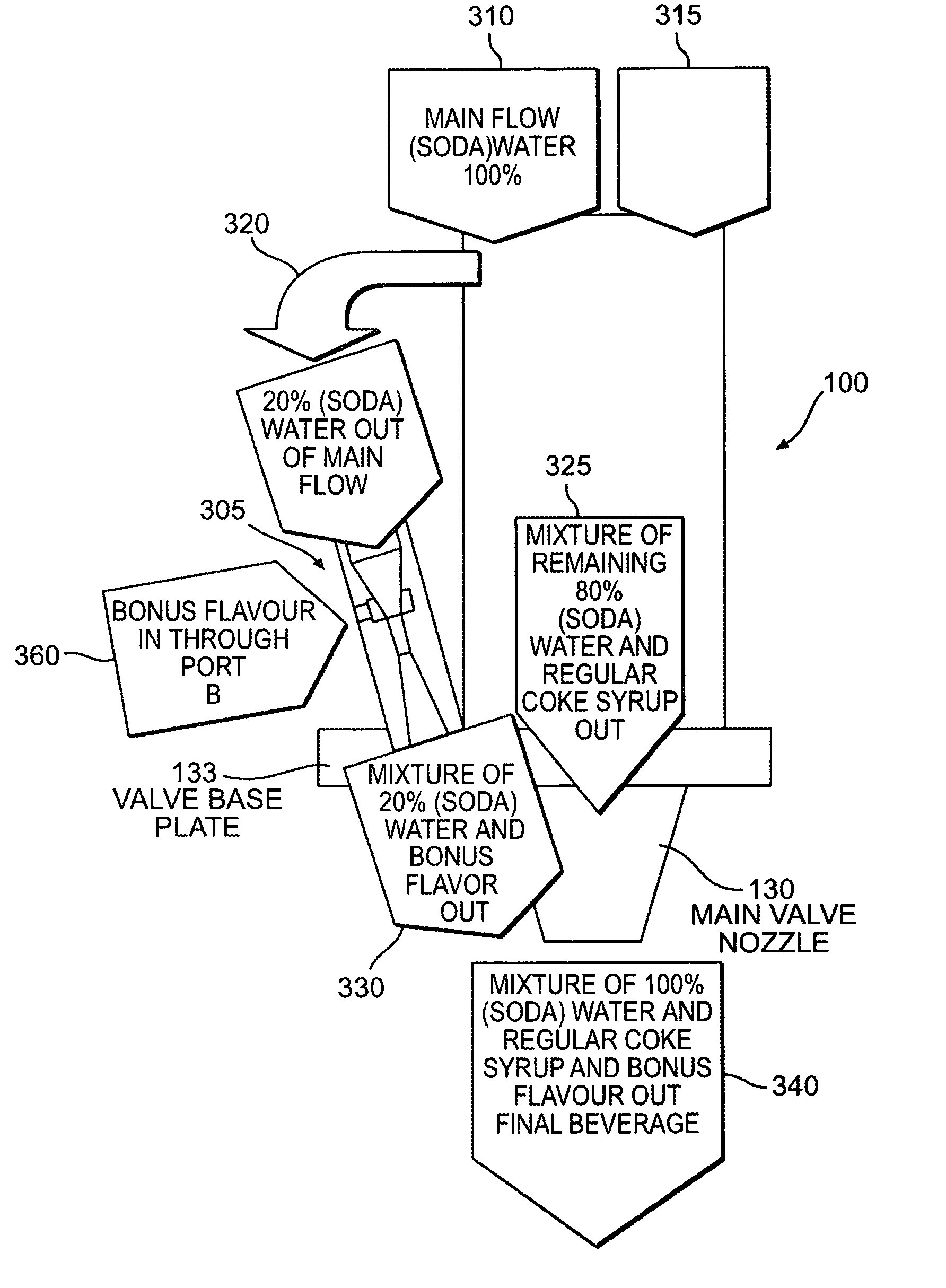
Figure 1 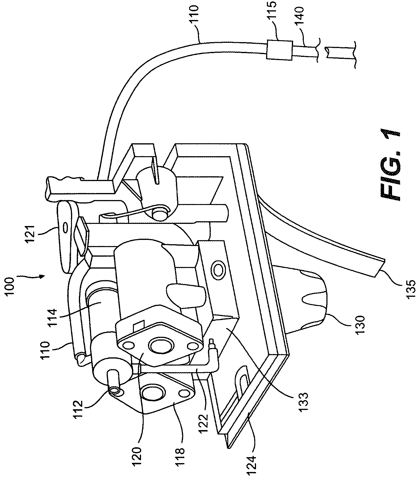
Figure 2 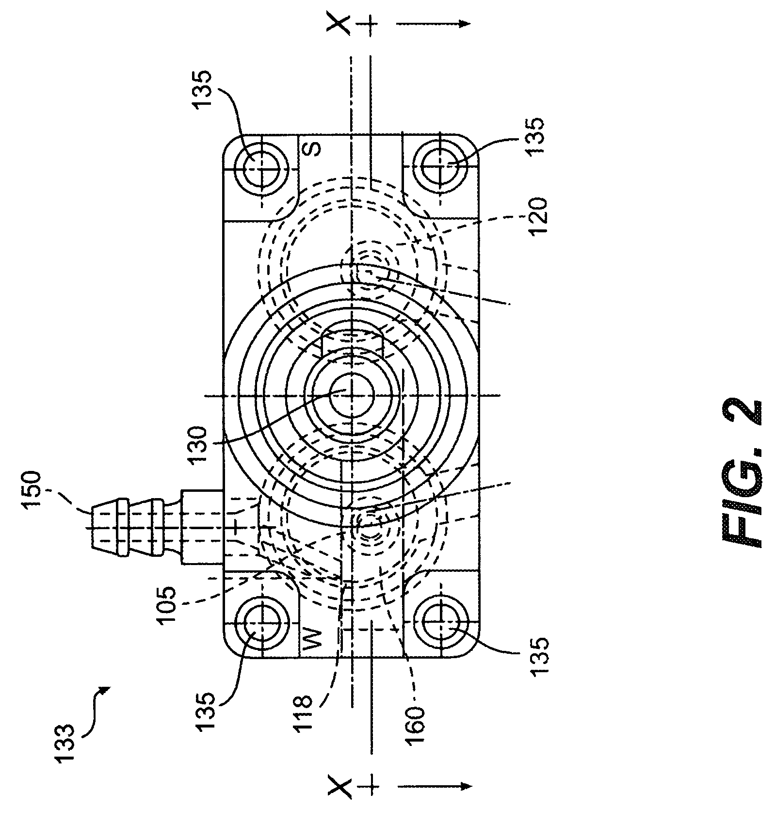
Figure 3
Abstract
Description
CROSS-REFERENCE TO RELATED APPLICATIONS
[0001] This application is a non-provisional application of U.S. Provisional Application No. 60 / 533,243, entitled “LIQUID DISPENSING DEVICE”, filed on Dec. 31, 2003, and is a continuation-in-part of U.S. patent application Ser. No. 10 / 370,074, filed Feb. 21, 2003 entitled “LIQUID DISPENSING DEVICE”, the disclosures of which are hereby incorporated by reference in their entireties.BACKGROUND
[0002] 1. Field of the Invention
[0003] The present invention relates generally to a soft drink dispensing machine. More specifically, the present invention relates to a soft drink dispensing machine device having a post mix dispensing head with an integrated bonus flavor Venturi valve. Even more specifically, the invention is directed to an external post mix dispensing head that utilizes motive energy from part of a water feed to entrain and mix a bonus flavor into a regular final beverage.
[0004] 2. Related Art
[0005] Soft drink dispensing machines are well known. ...
Examples
Embodiment Construction
[0042]Referring now to FIG. 1, there is shown a liquid dispenser 100 having a dispense nozzle 130 mounted to the underside of a manifold 124. Also included is a valve base 133, which can be a mollified base, mounted to the top side of manifold 124 and which houses a Venturi valve 105 as shown in greater detail in FIG. 3 and discussed in further detail below. A tube 122 is connected at its lower end to an input port 150 and, at is upper end, to a needle control valve 112. Needle control valve 112 may be controlled by a flow control means 114. Needle control valve 112 may be a solenoid, a toggle valve or suitable control valve.
[0043]Dispenser 100 also includes syrup flow control 120 and water flow control 118 connected to valve base 133. Also included on manifold 124 is solenoid 121, which selectively opens and closes water flow control 118 and syrup flow control 120. Nozzle 130 can be a two-part nozzle. Water is directed through water flow control 118 through a top part of nozzle 130...