
Method of making a semiconductor chip assembly with a bumped metal pillar
a metal pillar and semiconductor chip technology, applied in semiconductor devices, semiconductor/solid-state device details, electrical devices, etc., can solve the problems of significant cost and technical limitations, over-all cost saving, and significant cost of forming bumps on the pads, so as to reduce stress, facilitate manufacturing, and enhance mechanical support and protection
Patent Information
- Authority / Receiving Office
- US · United States
- Patent Type
- Patents(United States)
- Current Assignee / Owner
- Publication Date
- 2006-09-26
- Estimated Expiration
- Not applicable · inactive patent
Smart Images
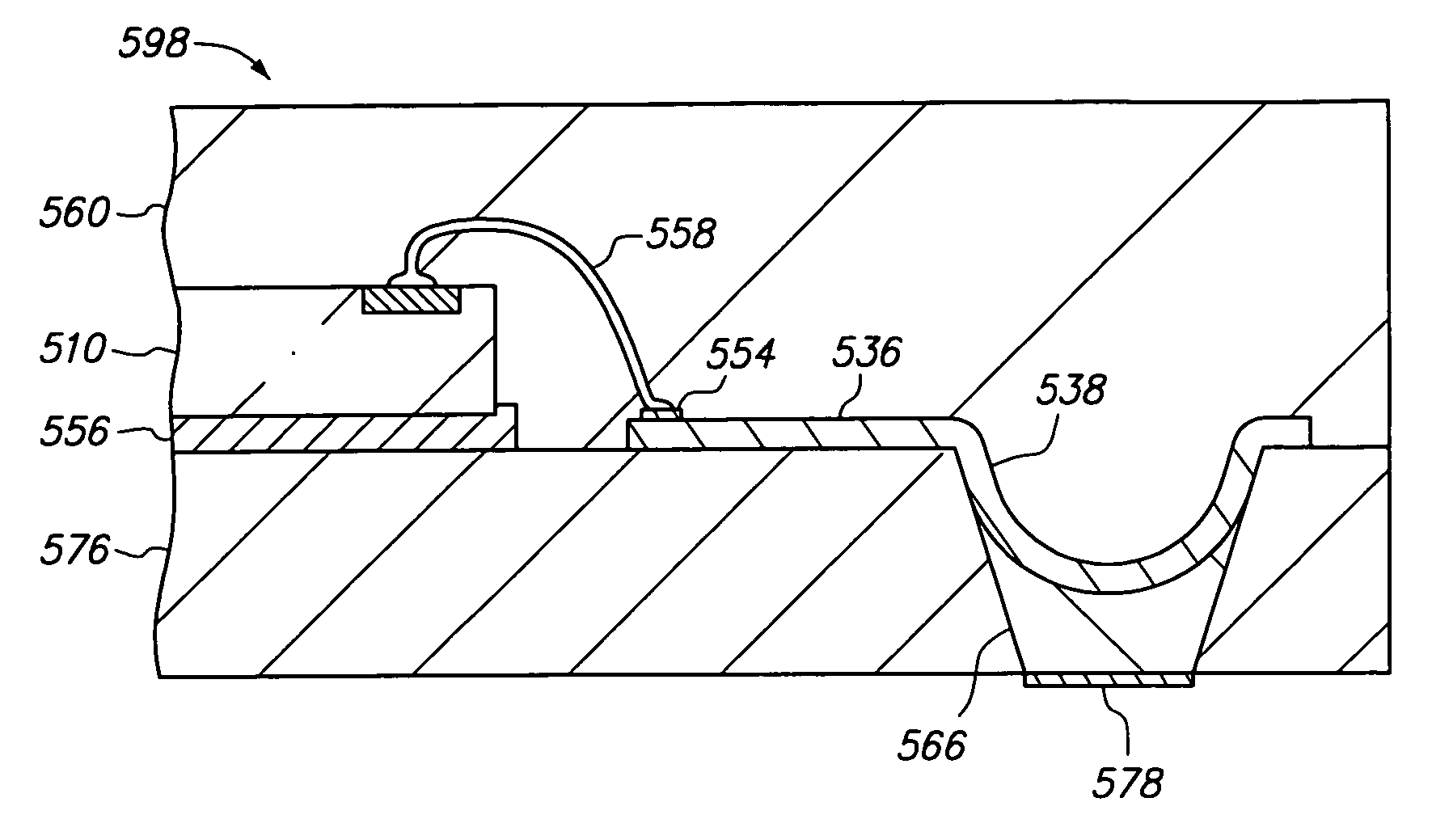
Figure 1 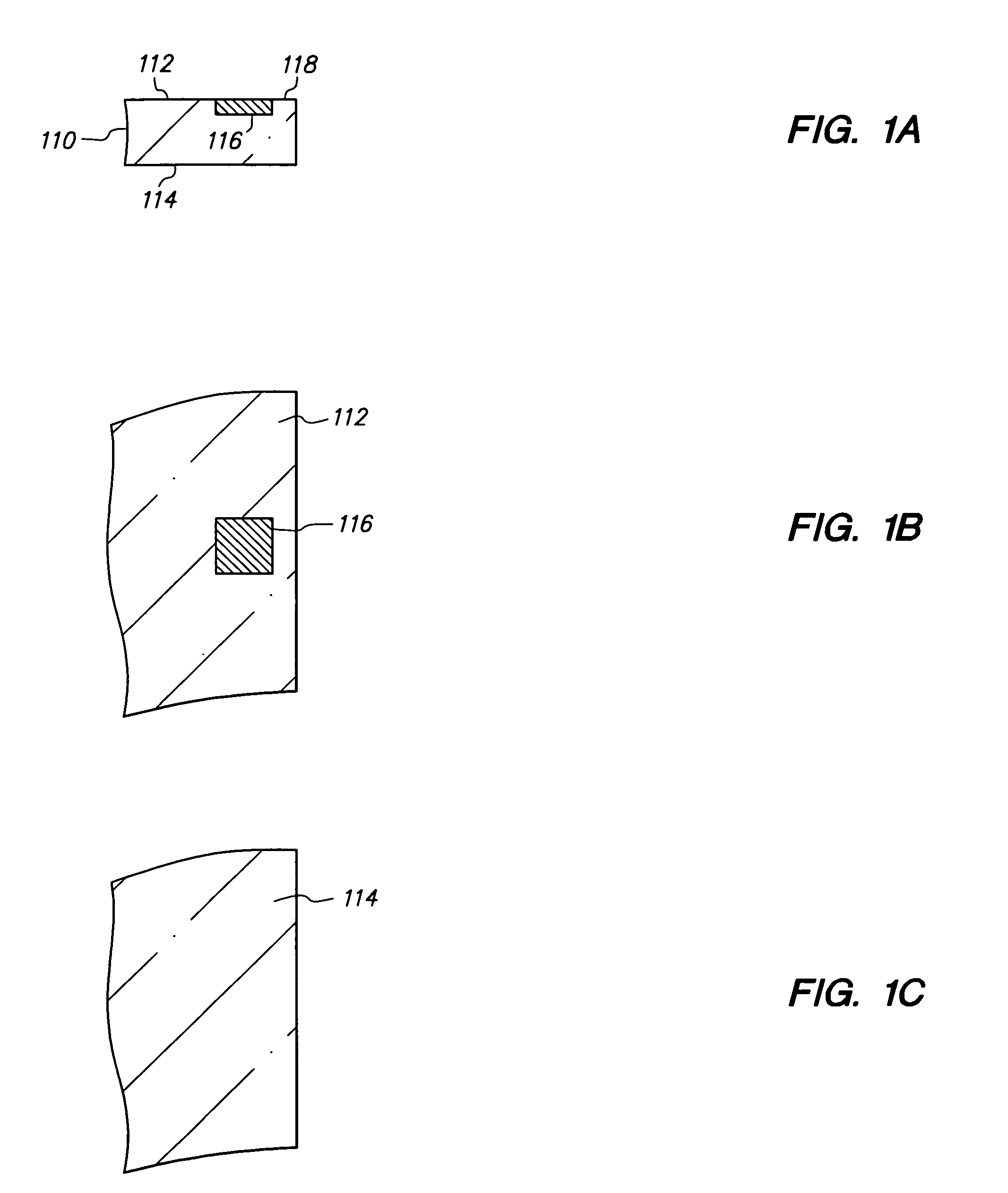
Figure 2 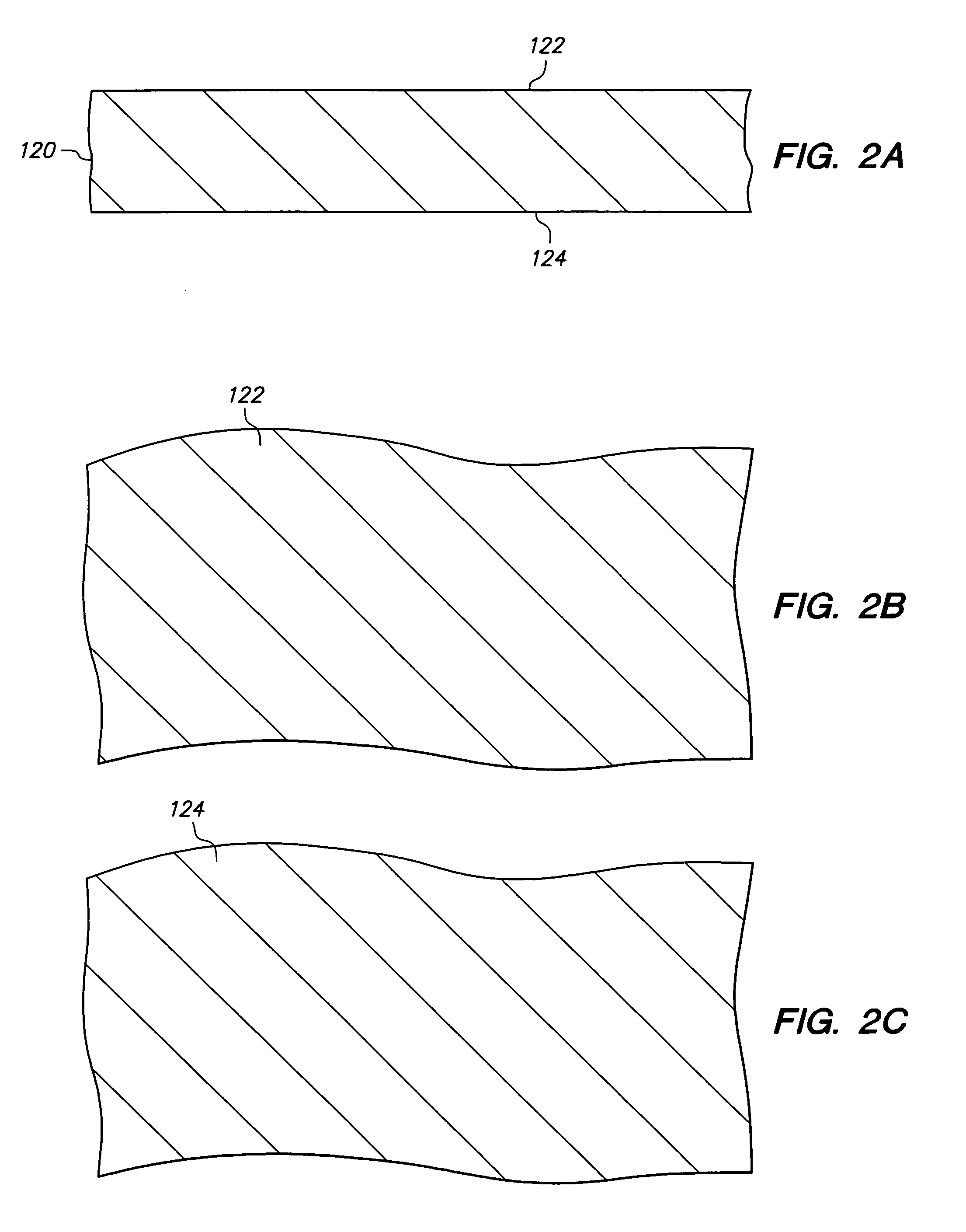
Figure 3
Abstract
Description
CROSS-REFERENCE TO RELATED APPLICATIONS
[0001] This application is a continuation of U.S. application Ser. No. 10 / 994,604 filed Nov. 22, 2004, which is a continuation-in-part of U.S. application Ser. No. 10 / 922,280 filed Aug. 19, 2004, which is a continuation-in-part of U.S. application Ser. No. 10 / 307,218 filed Nov. 29, 2002, and issued as U.S. Pat. No. 6,809,414 which is a divisional of U.S. application Ser. No. 09 / 997,973 filed Nov. 29, 2001, and issued as U.S. Pat. No. 6,492,252 which is a continuation-in-part of U.S. application Ser. No. 09 / 917,339 filed Jul. 27, 2001, U.S. Pat. No. 6,537,851 which is a continuation-in-part of U.S. application Ser. No. 09 / 878,626 filed Jun. 11, 2001, and issued as U.S. Pat. No. 6,653,217 which is a continuation-in-part of U.S. application Ser. No. 09 / 687,619 filed Oct. 13, 2000, and issued as U.S. Pat. No. 6,440,835 each of which is incorporated by reference.
[0002] U.S. application Ser. No. 10 / 994,604 filed Nov. 22, 2004 also claims the benefit of...
Examples
Embodiment Construction
[0077]FIGS. 1A–21A, 1B–21B and 1C–21C are cross-sectional, top and bottom views, respectively, of a method of making a semiconductor chip assembly in accordance with a first embodiment of the present invention.
[0078]FIGS. 1A, 1B and 1C are cross-sectional, top and bottom views, respectively, of semiconductor chip 110 which is an integrated circuit in which various transistors, circuits, interconnect lines and the like are formed (not shown). Chip 110 includes opposing major surfaces 112 and 114 and has a thickness (between surfaces 112 and 114) of 150 microns. Surface 112 is the active surface and includes conductive pad 116 and passivation layer 118.
[0079]Pad 116 is substantially aligned with passivation layer 118 so that surface 112 is essentially flat. Alternatively, if desired, pad 116 can extend above or be recessed below passivation layer 118. Pad 116 provides a bonding site to electrically couple chip 110 with external circuitry. Thus, pad 116 can be an input / output pad or a ...