
Branch prediction mechanism using a branch cache memory and an extended pattern cache
a branch cache and pattern cache technology, applied in the field of data processing systems, can solve the problems of large increase in the size of the memory required to store the predicted outcomes for each of those possible, change of program flow, and inability to accurately identify the effect of the circui
Patent Information
- Authority / Receiving Office
- US · United States
- Patent Type
- Patents(United States)
- Current Assignee / Owner
- Publication Date
- 2008-09-23
Smart Images
Figure 1 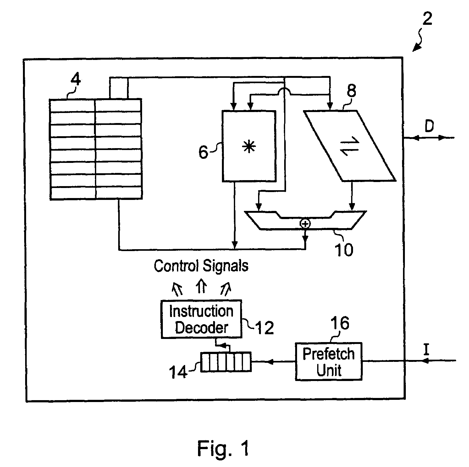
Figure 2 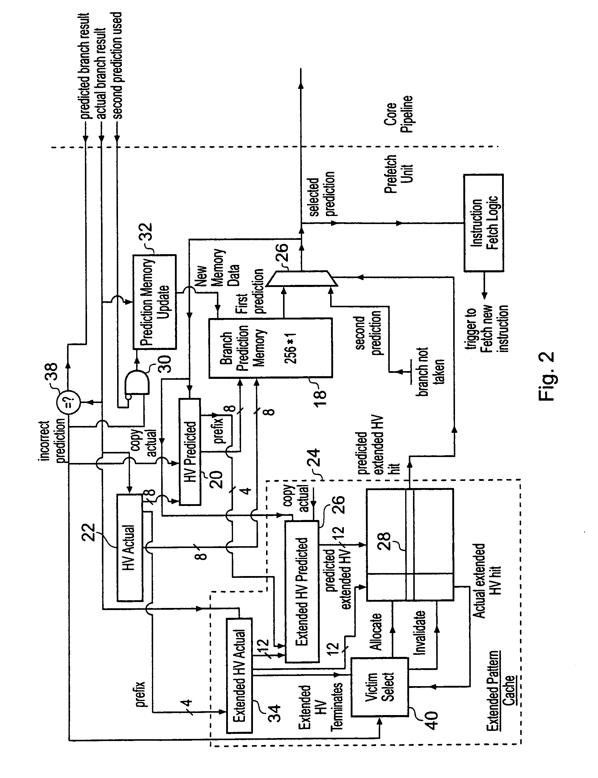
Figure 3
Abstract
Description
BACKGROUND OF THE INVENTION
[0001] 1. Field of the Invention
[0002] This invention relates to the field of data processing systems. More particularly, this invention relates to data processing systems including branch prediction mechanisms.
[0003] 2. Description of the Prior Art
[0004] It is known to provide data processing systems using a pipelined architecture in which multiple program instructions are subject to different stages of their processing within a sequence of pipeline stages. Instructions are fetched into the pipeline by a prefetch unit. A problem arises with conditional branch instructions which may or may not result in a change of program flow, this being unknown at the point at which they are inserted into the pipeline with subsequent instructions requiring to be fetched before it is actually determined whether or not the conditional branch will or will not be taken.
[0005] In order to deal with this situation, which can cause severe performance problems due to the requirement...
Examples
Embodiment Construction
[0042]FIG. 1 illustrates a data processing system 2, such as an embedded data processing core. The data processing system 2 as illustrated includes a register bank 4, a multiplier 6, a shifter 8, an adder 10, an instruction decoder 12, an instruction pipeline 14 and a prefetch unit 16. It will be appreciated that in practice the data processing system 2 will incorporate many more circuit elements. The circuit elements illustrated in FIG. 1 have been simplified and illustrate how instructions I are fetched by the prefetch unit 16 and then supplied to the instruction pipeline 14. Program instructions within the instruction pipeline 14 control an instruction decoder 12 which then generates control signals which configure the register bank 4, the multiplier 6, the shifter 8 and the adder 10 to perform desired data processing operations.
[0043]FIG. 2 schematically illustrates a part of the prefetch unit 12 that deals with branch prediction. This includes a branch prediction memory 18 whic...