
Rotational coupling device
a technology of rotating coupling and coupling shaft, which is applied in the direction of magnetically actuated clutches, mechanical actuators, mechanical apparatuses, etc., can solve the problems of conventional rotational coupling devices, and achieve the effect of increasing torque transfer and widening clearan
Patent Information
- Authority / Receiving Office
- US · United States
- Patent Type
- Patents(United States)
- Current Assignee / Owner
- Publication Date
- 2009-05-05
Smart Images
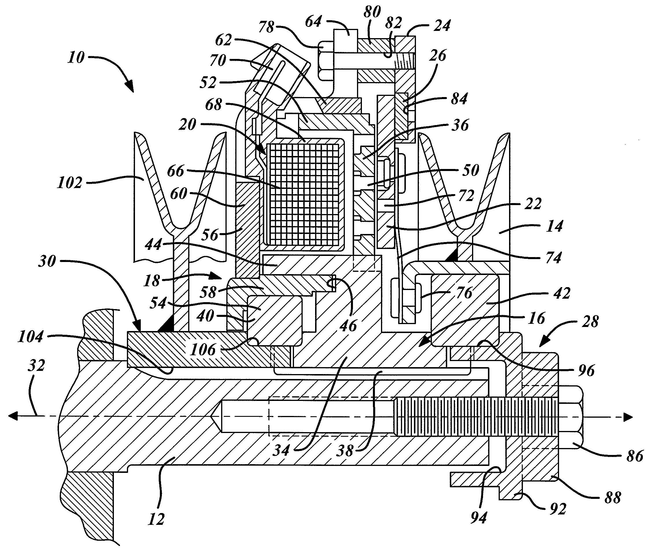
Figure 1 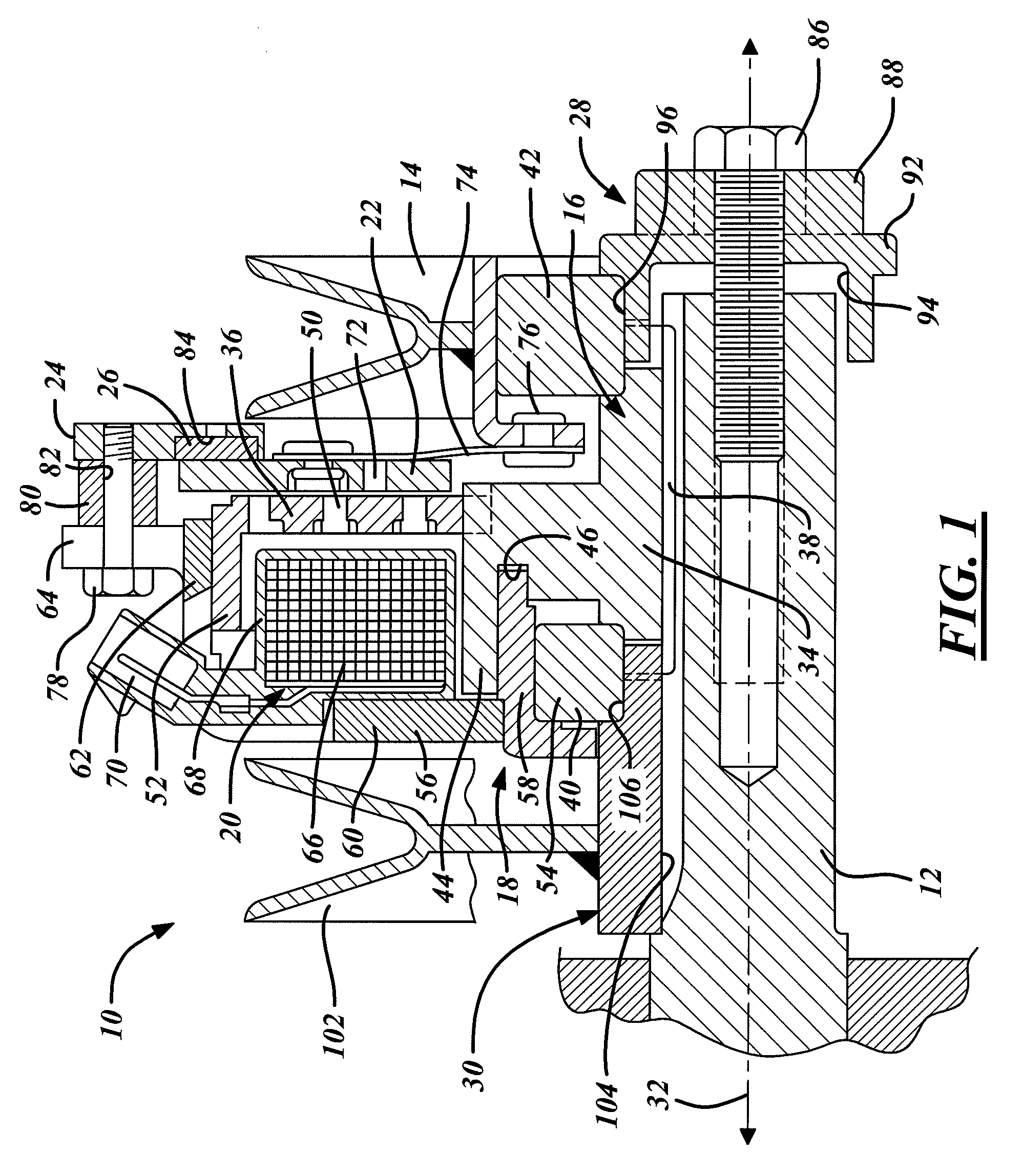
Figure 2 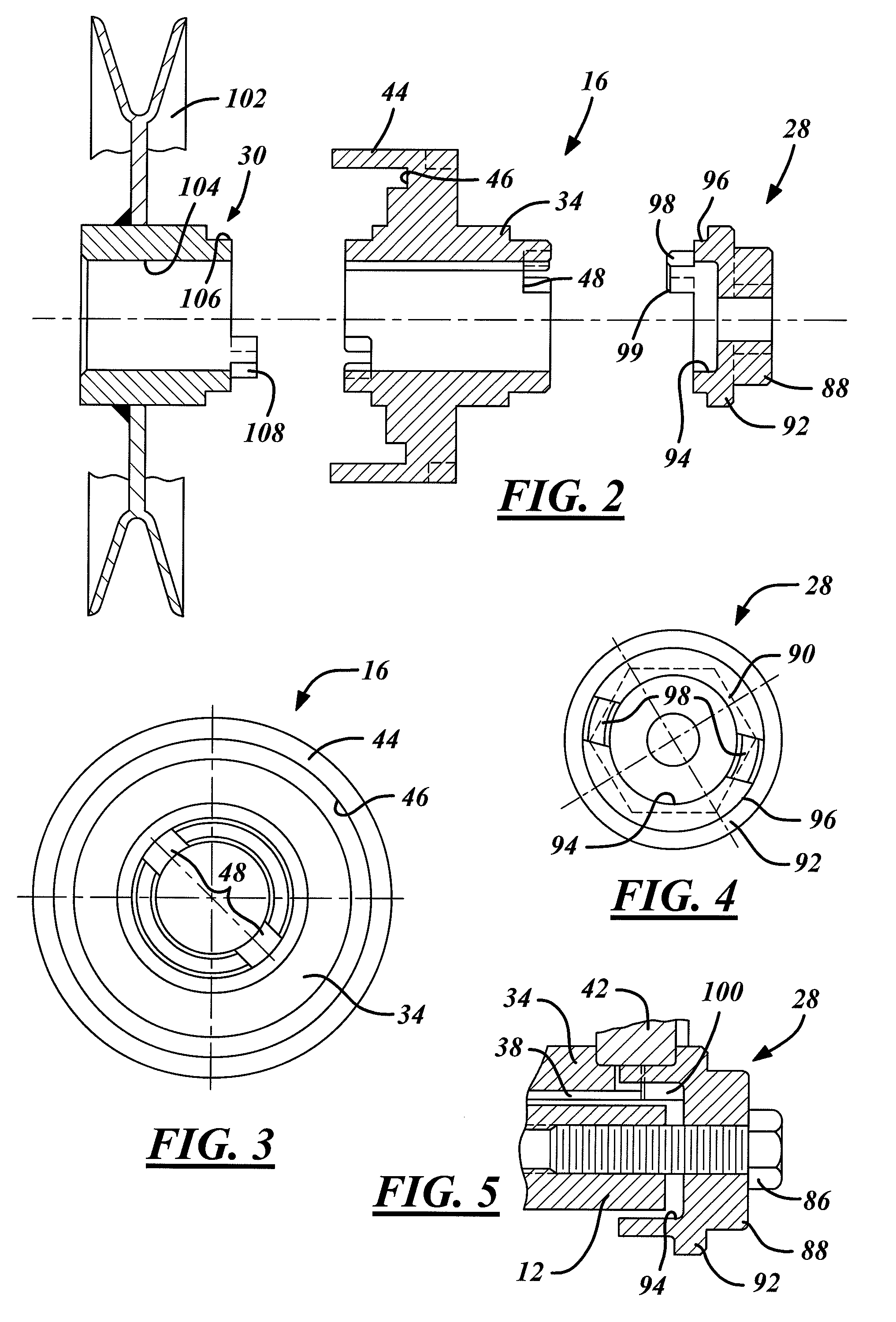
Figure 3
Abstract
Description
BACKGROUND OF THE INVENTION
[0001] 1. Field of the Invention
[0002] This invention relates to rotational coupling devices such as brakes and clutches and, in particular, to a rotational coupling device that provides enhanced torque transfer characteristics through an inventive coupling arrangements of components within the device.
[0003] 2. Discussion of Related Art
[0004] Rotational coupling devices such as clutches and brakes are used to control transfer of torque between rotational bodies. One type of conventional device is illustrated in U.S. Pat. Nos. 5,119,918, 5,285,882 and 5,971,121, the entire disclosures of which are incorporated herein by reference. This device includes a rotor that is coupled to an input shaft for rotation with the input shaft about a rotational axis. A field shell is also disposed about the input shaft on one side of the rotor and is fixed against rotation. The field shell defines radially spaced, axially extending inner and outer poles between which an electri...
Examples
Embodiment Construction
[0021]Referring now to the drawings wherein like reference numerals are used to identify identical components in the various views, FIG. 1 illustrates a rotational coupling device 10 in accordance with one embodiment of the present invention. Device 10 functions as a clutch to selectively transfer torque from an input shaft 12 to an output member 14. Device 10 also functions as a brake on output member 14 when torque is not being transferred to output member 14. Device 10 may be provided for use in a riding lawnmower or similar device. It will be understood by those of ordinary skill in the art, however, that device 10 may be used in a wide variety of applications requiring a clutch or brake. Device 10 may include a rotor 16, a field shell 18, an electrical conduction assembly 20, an armature 22, a brake pole 24, one or more permanent magnets 26 and one or more support members such as spacer 28 or pulley hub 30.
[0022]Input shaft 12 provides a source of torque for driving output memb...