
Multi-band or wide-band antenna including driven and parasitic top-loading elements
a top-loading element and antenna technology, applied in the direction of radiating element structure, elongated active element feed, resonance antenna, etc., can solve the problems of increasing the cost of antenna design to reduce size, increasing the cost of antenna design today, and high dielectric constant materials, etc., to achieve economic manufacturing and reduce the size of additional antennas
Patent Information
- Authority / Receiving Office
- US · United States
- Patent Type
- Patents(United States)
- Current Assignee / Owner
- Publication Date
- 2010-06-08
- Estimated Expiration
- Not applicable · inactive patent
Smart Images
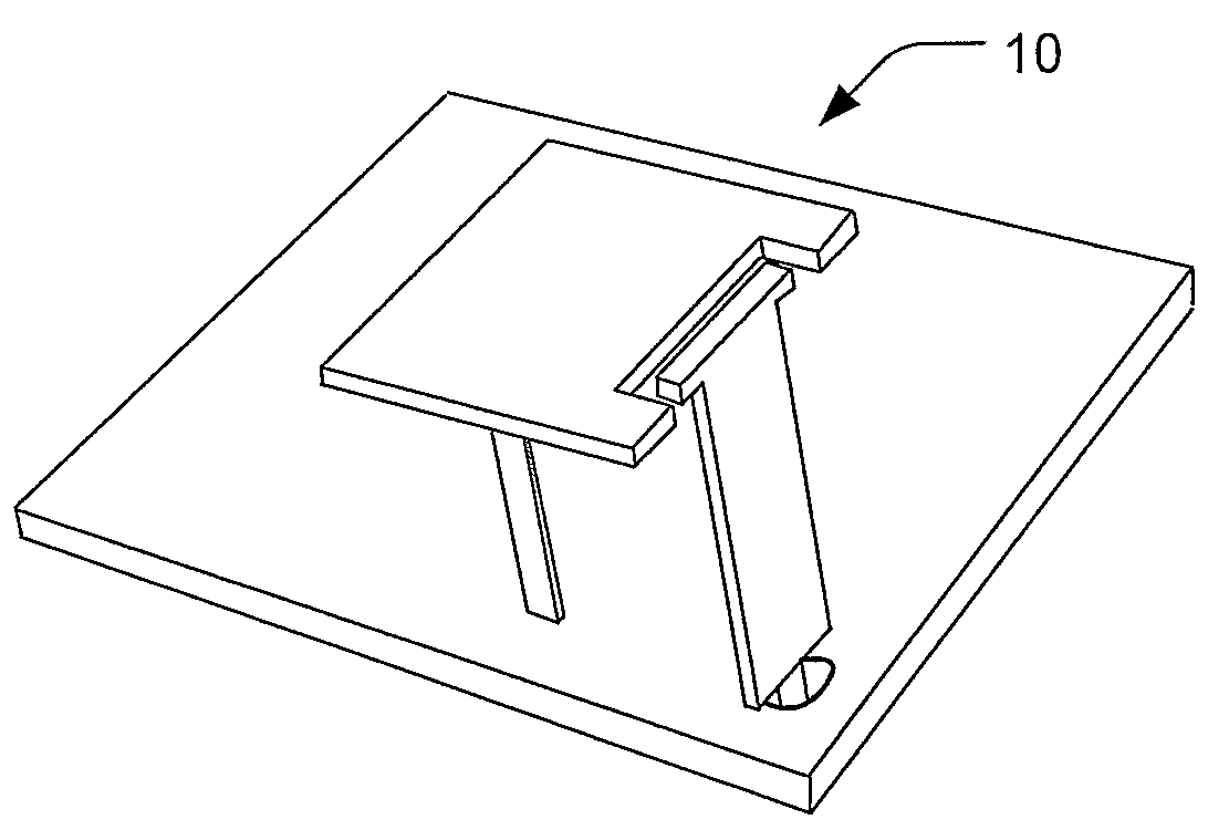
Figure 1 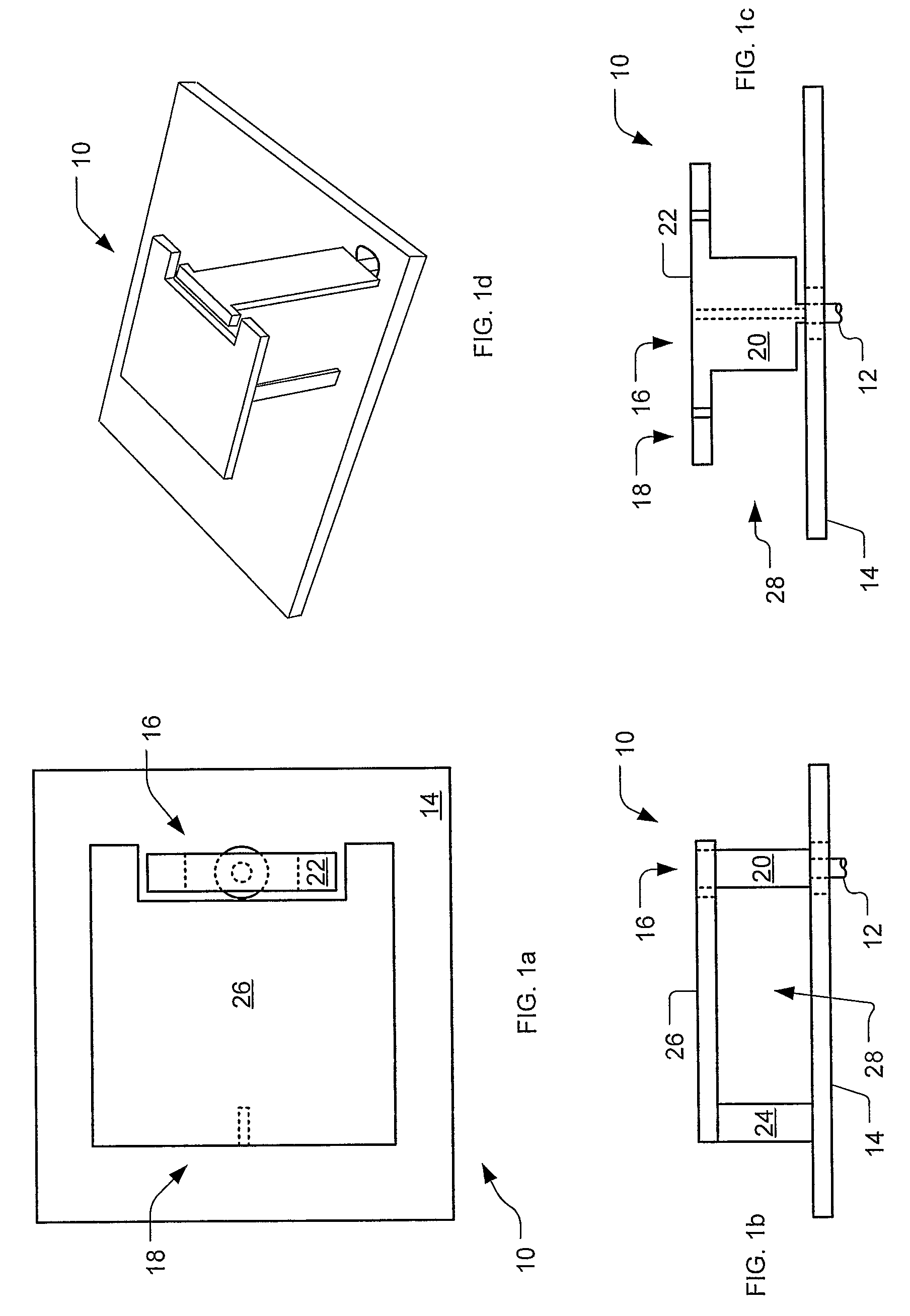
Figure 2 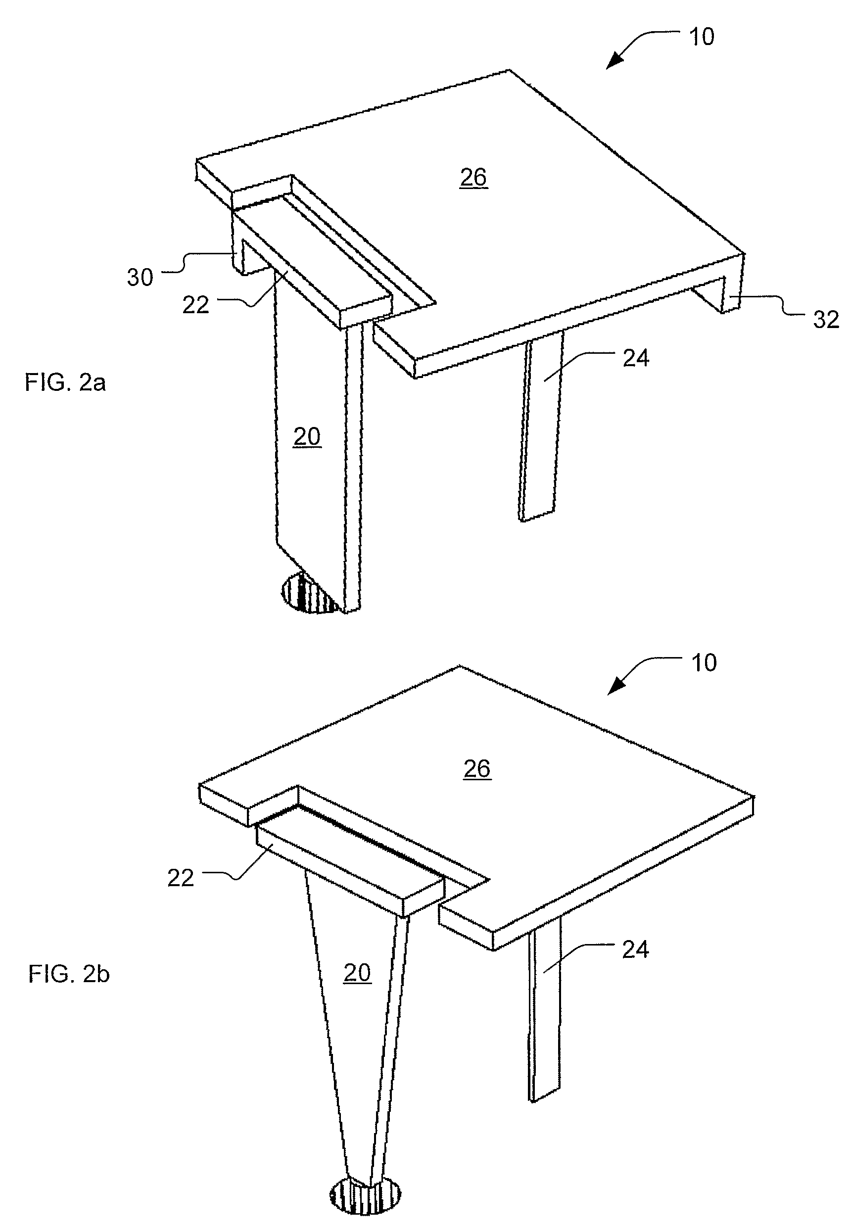
Figure 3
Abstract
Description
TECHNICAL FIELD
[0001] The present invention relates generally to radio wave antennas, and more particularly to such with lumped reactance at the free end for loading the antenna. It is anticipated that this invention will particularly be used with small and wireless communication devices.BACKGROUND ART
[0002] Antennas for wireless communication equipment, for example pagers, cell phones and WLAN access points must be small in size, light in weight, compact in physical volume, and cheap to manufacture. Flush mounted or built-in internal antennas are therefore often desired or even required. Also, devices that communicate with wireless services often must operate in different frequency bands, due to different geographical band allocation schemes, different wireless providers, different wireless services, or different wireless communication protocols. Such devices accordingly require an antenna or multiple antennas that are responsive to multiple frequency bands. A single antenna is prefe...
Examples
Embodiment Construction
[0027]A preferred embodiment of the present invention is a multi-band antenna. As illustrated in the various drawings herein, and particularly in the view of FIGS. 1a-d, preferred embodiments of the invention are depicted by the general reference character 10.
[0028]As is common practice in this art when antennas capable of use for transmission and reception are discussed, we herein label elements and describe their roles in the context of transmission. Those skilled in the art will readily appreciate that the same elements can nonetheless also serve in reception.
[0029]FIGS. 1a-d, respectively, depict a top plan view, a left side view, a front side view, and a perspective view of an embodiment of the inventive antenna 10 that is in accord with the present invention. The antenna 10 here includes a feed point 12, a grounding conductor or grounding surface 14, a driven radiating section 16, and a parasitic radiating section 18.
[0030]The driven radiating section 16 includes a feed conduc...