
Sliding contact guide for transmission device
a contact guide and transmission device technology, applied in the direction of belts/chains/gearrings, mechanical equipment, etc., can solve the problems of difficult control of the finished product size, difficult to remove heat from the central portion of the chain contact surface during molding, and prone to deformation, so as to achieve uniform cooling, suppress deformation of the shoe due to thermal shrinkage following molding, and adequate strength
Patent Information
- Authority / Receiving Office
- US · United States
- Patent Type
- Patents(United States)
- Current Assignee / Owner
- Publication Date
- 2011-08-30
Smart Images
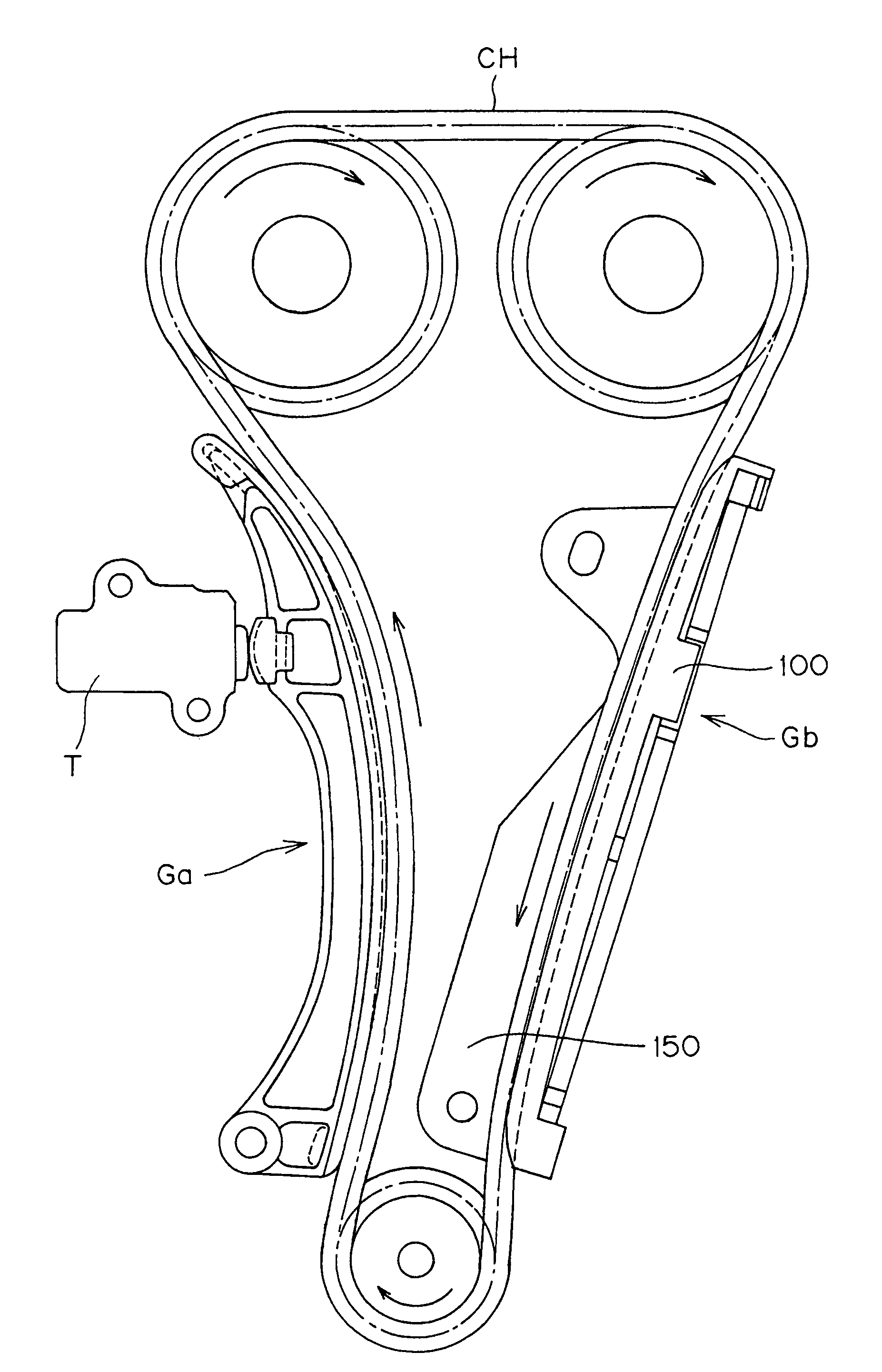
Figure 1 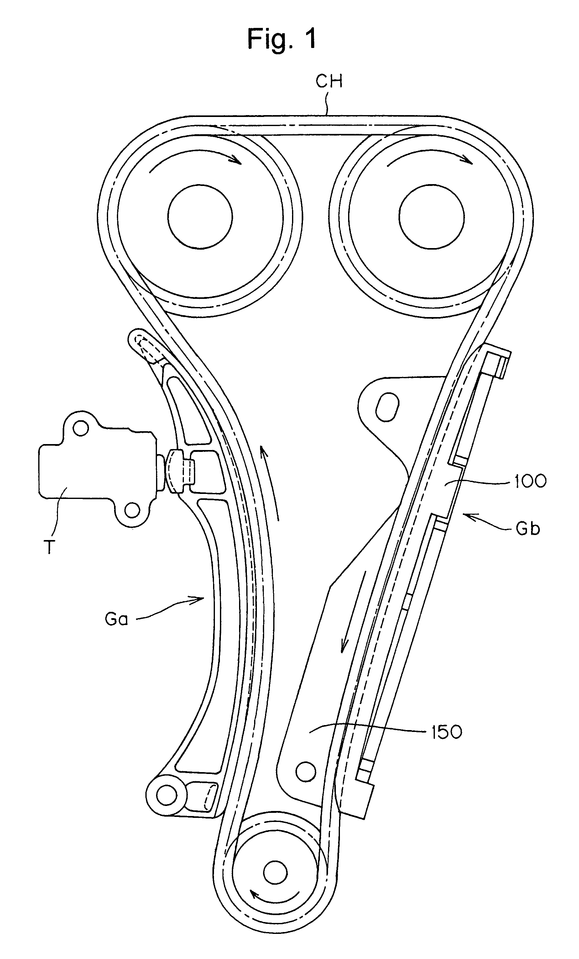
Figure 2 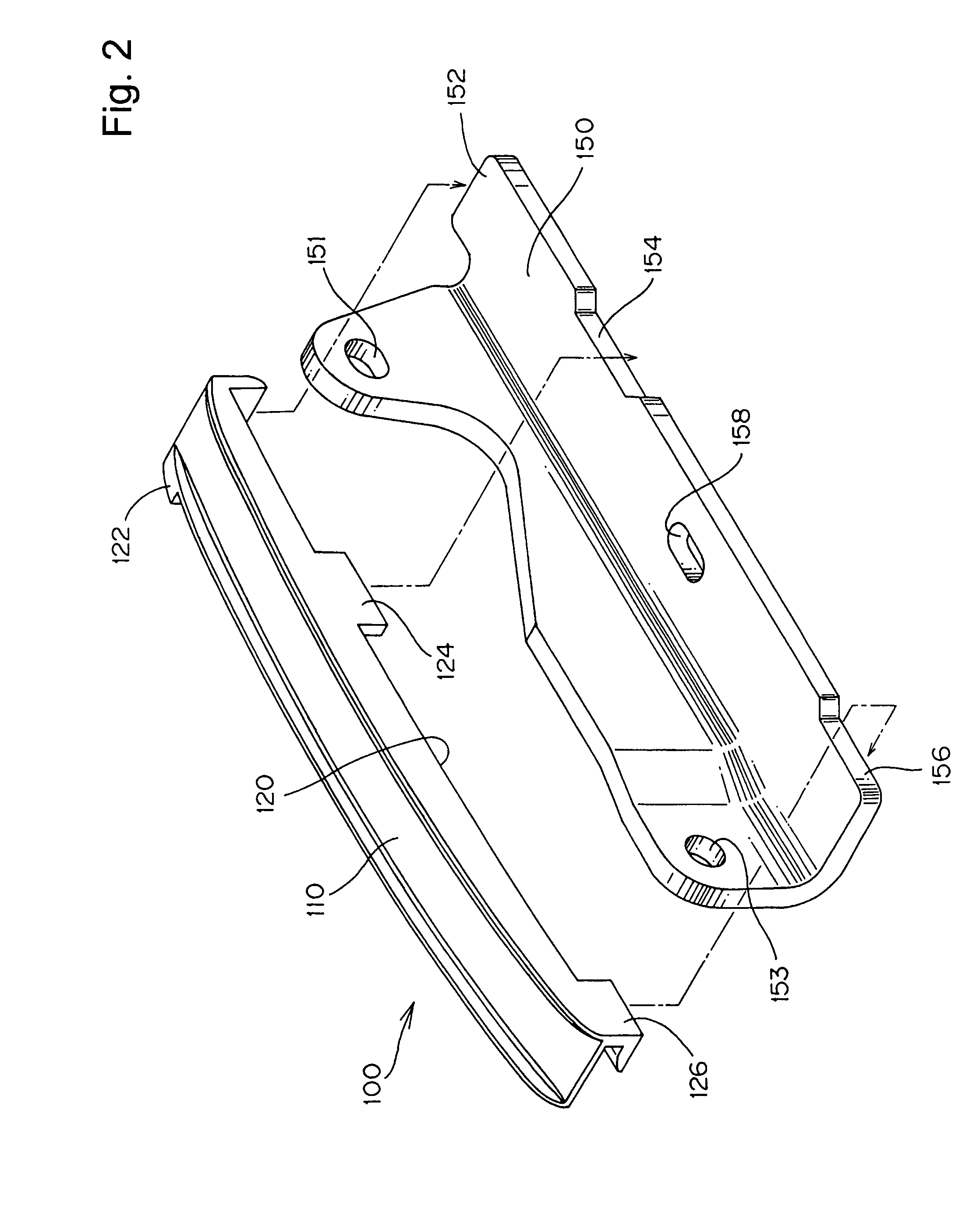
Figure 3
Abstract
Description
FIELD OF THE INVENTION
[0001] This invention relates to a sliding contact guide for a flexible, traveling, transmission medium, used to transmit power from a driving shaft to one or more driven shafts in a transmission mechanism such as the timing drive of an internal combustion engine.BACKGROUND OF THE INVENTION
[0002] An automobile engine generally includes a transmission device, which utilizes an endless, traveling, flexible, transmission medium, such as a roller chain, silent chain, toothed belt, or the like, to transmit rotation from the engine crankshaft to one or more valve-operating camshafts. In such a transmission device, sliding contact guides are used to guide the chain. Typically, a fixed guide is disposed in sliding engagement with the tension side of the chain, i.e., the side moving from a driven sprocket to the driving sprocket, and a movable guide is disposed in sliding engagement with the slack side of the chain, i.e., the side moving from the driving sprocket to a dri...
Examples
Embodiment Construction
[0017]In the transmission shown in FIG. 1, a movable guide Ga and a fixed guide Gb, are provided respectively on the slack and tension sides of a drive chain CH arranged to be driven by a crankshaft sprocket and to drive two camshaft sprockets. The movable guide is pivoted, and urged by a tensioner T into sliding contact with the chain.
[0018]The movable guide Ga and the fixed guide Gb are similar, differing from each other primarily only in their shapes and in the methods by which they are attached to the engine block. The characterizing features of the invention reside in the structure of the backs of resin shoes of the guides, and will be described with reference to the fixed guide Gb. It should be understood, however, that the invention is applicable to movable guides as well as to fixed guides
[0019]As shown in FIG. 2, a metal guide base 150 is provided with a flange having mounting holes 151 and 153 for receiving bolts by which the base can be secured to an engine block.
[0020]Re...