

Exercise support device, exercise support method and recording medium
a technology of exercise support and support device, applied in gymnastics, television systems, instruments, etc., can solve the problems of large installation site, large installation site, and considerable effort required for continuous exercise for a long time, and achieve the effect of reducing the economic burden of the user and saving spa
Patent Information
- Authority / Receiving Office
- US · United States
- Patent Type
- Patents(United States)
- Current Assignee / Owner
- Publication Date
- 2011-08-30
- Estimated Expiration
- Not applicable · inactive patent
Smart Images
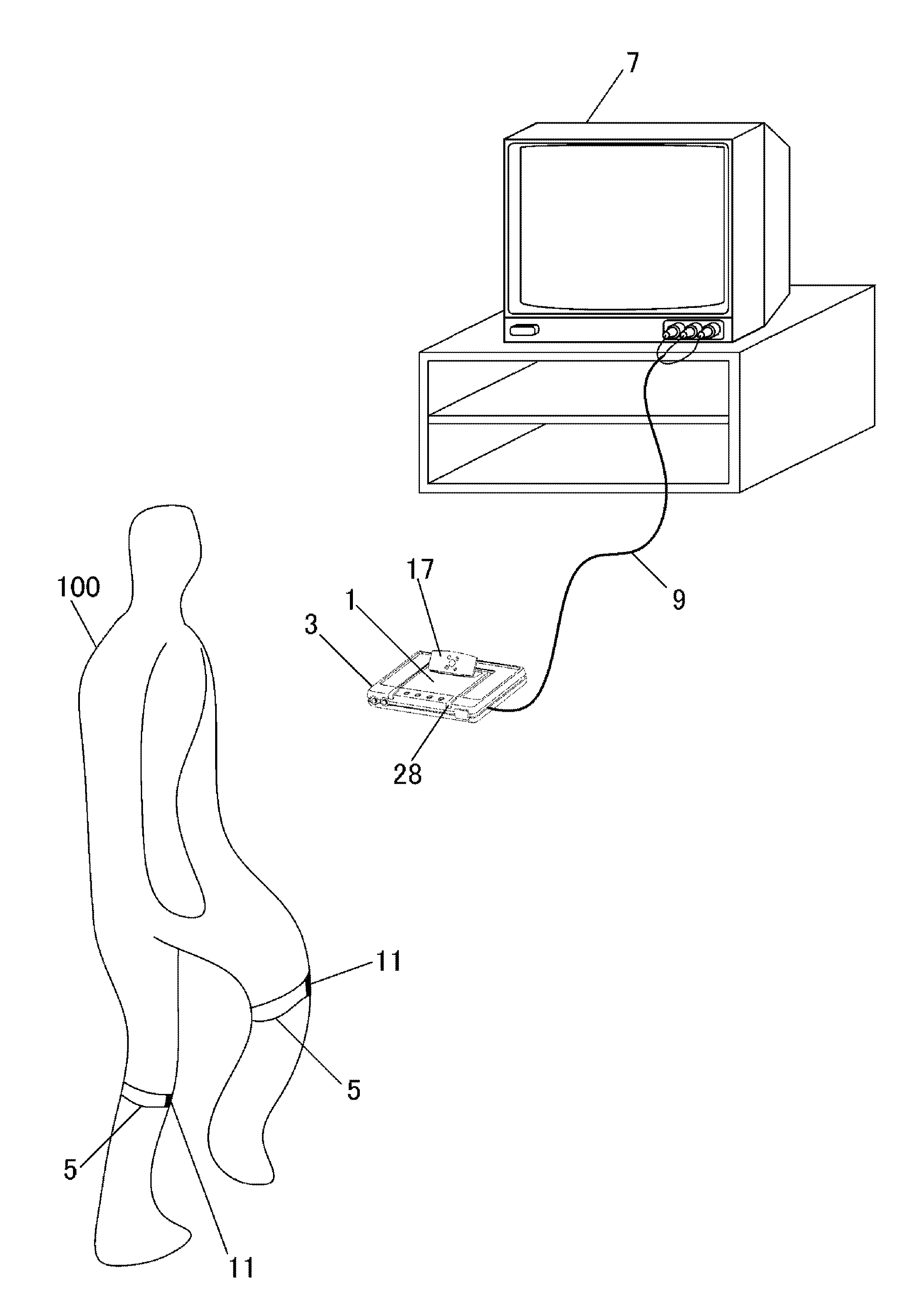
Figure 1 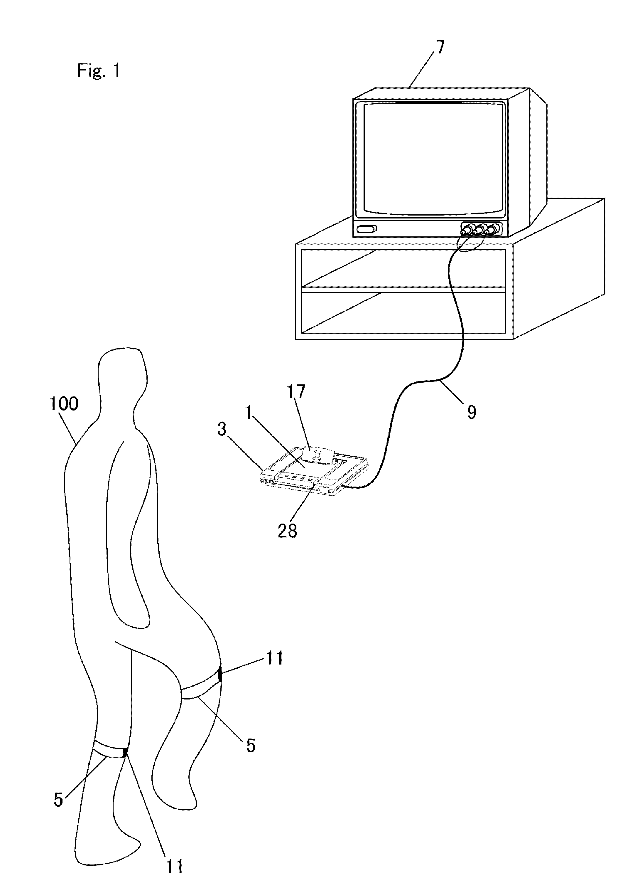
Figure 2 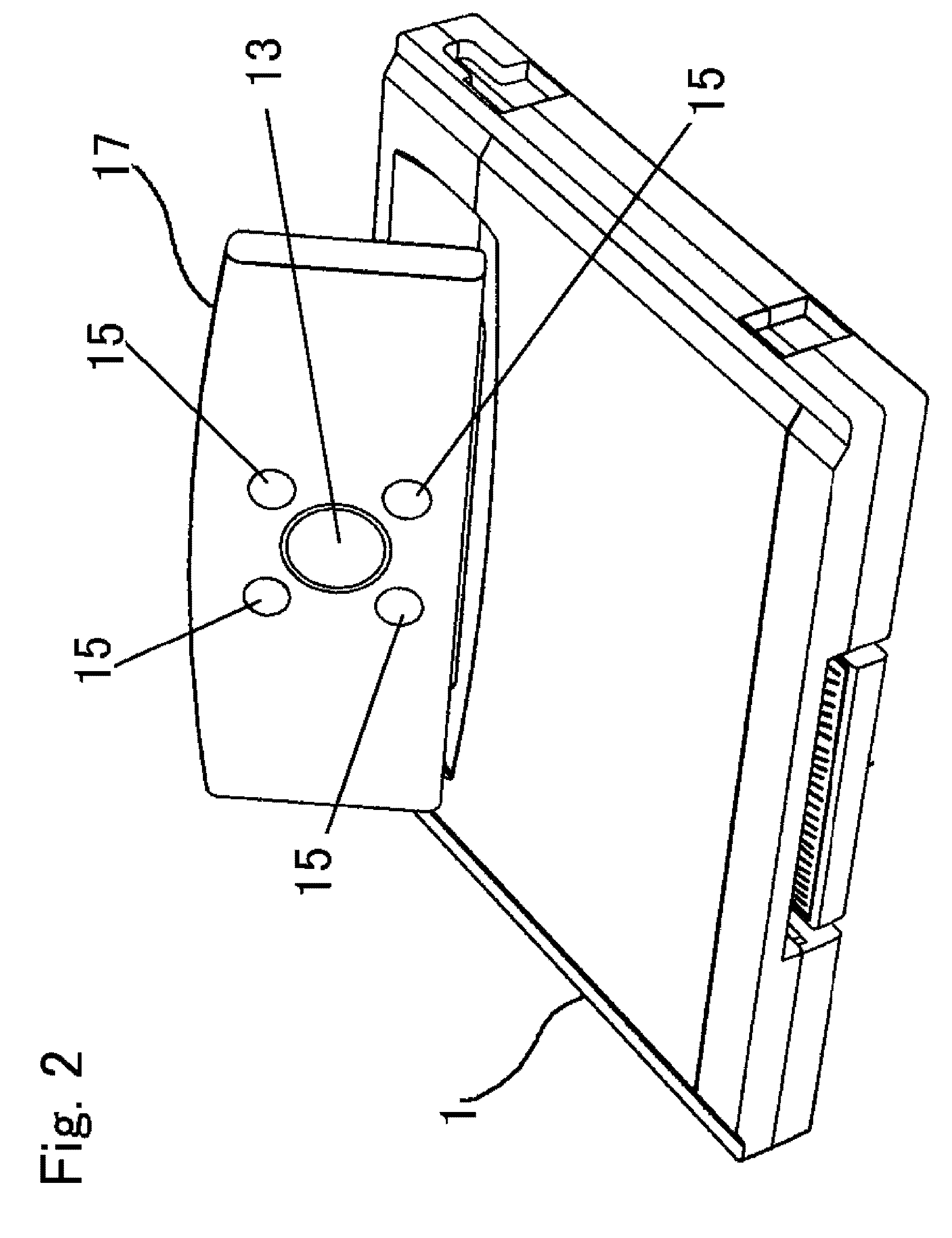
Figure 3
Abstract
Description
BACKGROUND OF THE INVENTION
[0001] 1. Field of the Invention
[0002] The present invention relates to an exercise support device and the related arts for supporting a stepping exercise.
[0003] 2. Description of the Related Art
[0004] The Patent Document 1 (Jpn. unexamined patent publication No. Hei 6-91018) discloses a stepper where a user places a left foot and right foot on a left pedal and a right pedal respectively to push them down alternately at left and right sides. In this way, the stepper exercises the user. Since the stepping exercise using the stepper is monotonous, considerable effort is required for performing continuously for a long period of time. The same is true for an exercise using a cycling machine.
[0005] Therefore, in the Patent Document 2 (Jpn. unexamined patent publication No. 2003-205051), a special computer links a cycling machine with a monitor and displays a video image in accordance with movements of pedals on the monitor, and thereby an exercise support device cap...
Examples
Embodiment Construction
[0043]FIG. 1 is a schematic diagram showing the entire configuration of an exercise support system in accordance with an embodiment of the present invention. As shown in FIG. 1, this exercise support system is provided with input instruments 5 which are worn on the left and right legs of a player 100, a cartridge 1 with an imaging unit 17, an adaptor 3 with a cancel key 28, and a television monitor 7. The cartridge 1 is electrically connected into the adaptor 3. Also, the adaptor 3 is connected with the television monitor 7 by an AV cable 9.
[0044]FIG. 2 is a perspective view of the cartridge 1 of FIG. 1. As shown in FIG. 2, the cartridge consists of a body in the form of a flat rectangular parallelepiped and the imaging unit 17. The imaging unit 17 is fixed on the upper surface of the body of the cartridge 1. In this case, the imaging unit 17 is fixed in such a manner that the surface thereof inclines by a predetermined angle (e.g., 40 degrees) to the surface of the cartridge 1. The...