
Manufacturing method of an outer ring for a bearing unit
a technology of bearing unit and outer ring, which is applied in the direction of manufacturing tools, heat treatment equipment, furniture, etc., can solve the problems of unnecessarily large wheel-supporting bearing unit, adverse effect on traveling stability and braking performance of automobiles, and increase in weight, so as to achieve convenient manufacturing, improve the degree of freedom in designing the grinding tool, and achieve the effect of convenient operation
Patent Information
- Authority / Receiving Office
- US · United States
- Patent Type
- Patents(United States)
- Current Assignee / Owner
- Publication Date
- 2013-01-01
- Estimated Expiration
- Not applicable · inactive patent
Smart Images
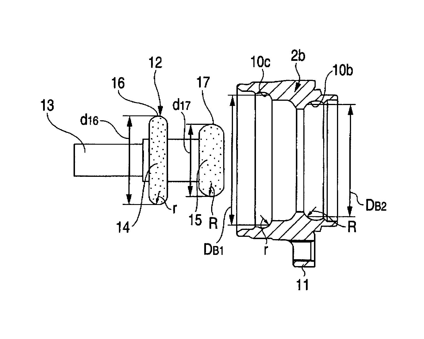
Figure 1 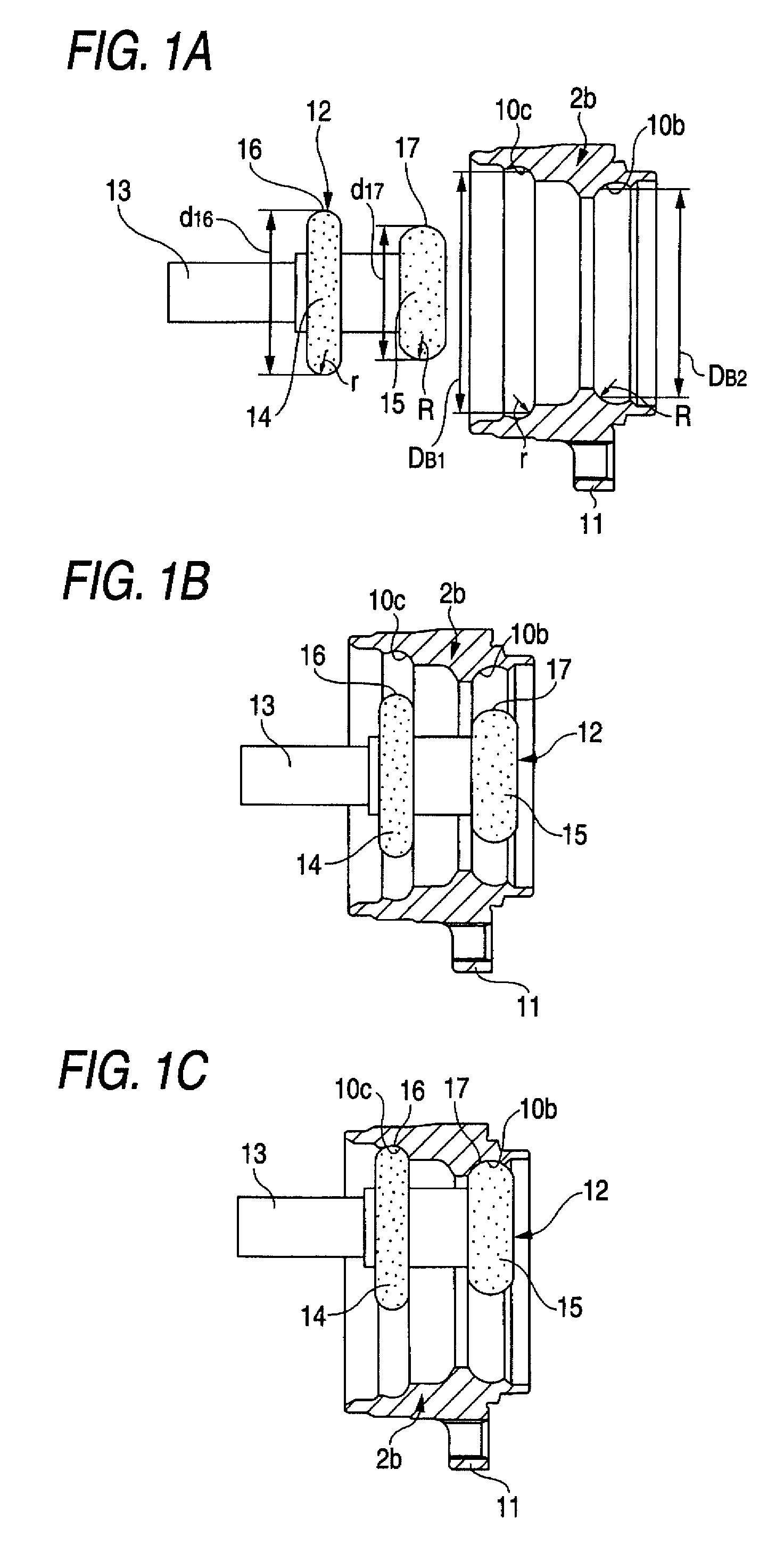
Figure 2 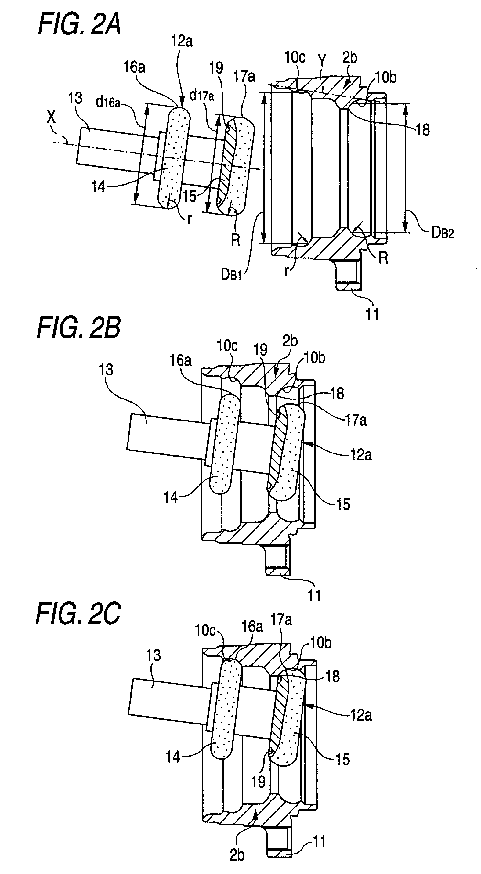
Figure 3
Abstract
Description
TECHNICAL FIELD
[0001] A manufacturing method of an outer ring for a bearing unit of the invention is used for manufacturing outer rings which make up various types of bearing units, such as a wheel-supporting bearing unit which is used for rotatably supporting an automotive wheel to a suspension device.BACKGROUND ART
[0002] A wheel of an automobile and a rotating member in a brake system are rotatably supported to a suspension device via a wheel-supporting bearing unit. FIG. 4 shows an example of a conventionally known wheel-supporting bearing unit. This wheel-supporting bearing unit includes a hub 1, an outer ring 2, and a plurality of balls 3 which are rolling elements. The hub 1 is formed by combining together a hub body 4 and an inner ring 5.
[0003] The hub body 4 has a mounting flange 6 disposed on a portion near to an outer end of an outer peripheral surface of the hub body 4 and adapted to support the automotive wheel and the rotating member for brake system; a first inner ring ra...
Examples
first embodiment
[0050]FIG. 1 shows a first embodiment of the invention corresponding to first and second aspects of the invention. An outer ring 2b to be manufactured is a component member of the wheel-supporting bearing unit shown in FIG. 6. Namely, this outer ring 2 has a first and a second outer ring raceway 10c and 10b formed in its inner peripheral surface and a coupling flange 11 formed on its outer peripheral surface for coupling to a suspension device. In addition, the diameter DB1 of the first outer ring raceway 10c is set to be greater than the diameter DB2 of the second outer ring raceway 10b (DB1>DB2) and the radius of curvature “r” of the cross-section profile of the first outer ring raceway 10c is set to be smaller than the radius of curvature “R” of the cross-section profile of the second outer ring raceway 10b (r<R).
[0051]A grinding tool 12, which is used for subjecting the both outer ring raceways 10c and 10b to a grinding process, is formed such that a first grinding wheel 14 and ...
second embodiment
[0067]Next, FIG. 2 shows a second embodiment of the invention corresponding to first through third aspects of the invention. In this embodiment, an outside diameter d16a of a first working surface 16a and an outside diameter d17a of a second working surface 17a, which surfaces constitute a grinding tool 12a, are made mutually equal (d16a=d17a). In addition, the pitch between the both first and second working surfaces 16a and 17a with respect to the axial direction is defined such that the both first and second working surfaces 16a and 17a are simultaneously brought into registration and contact with the both first and second outer ring raceways 10c and 10b in a state in which a center axis of the grinding tool 12a is inclined with respect to the center axis of the outer ring 2b, as shown in FIG. 2(C) which will be referred to later.
[0068]In this embodiment, when the both first and second outer ring raceways 10c and 10b are subjected to the grinding process by using such a grinding t...
third embodiment
[0072]Next, FIG. 3 shows a third embodiment of the invention corresponding to fifth aspect of the invention. In this embodiment as well, the outer ring 2b to be manufactured is a component member of the wheel-supporting bearing unit shown in FIG. 6. Namely, this outer ring 2 has the first and the second outer ring raceway 10c and 10b formed in its inner peripheral surface and the coupling flange 11 formed on its outer peripheral surface for coupling to the suspension device. In addition, the diameter DB1 of the first outer ring raceway 10c is set to be greater than the diameter DB2 of the second outer ring raceway 10b (DB1>DB2) and the radius of curvature “r” of the cross-section profile of the first outer ring raceway 10c is set to be smaller than the radius of curvature “R” of the cross-section profile of the second outer ring raceway 10b (r<R).
[0073]In addition, a high-frequency heating tool 20, which is used for subjecting the both outer ring raceways 10c and 10b to high-frequen...