
Flow control device
Patent Information
- Authority / Receiving Office
- US · United States
- Patent Type
- Patents(United States)
- Current Assignee / Owner
- Publication Date
- 2014-01-21
Smart Images
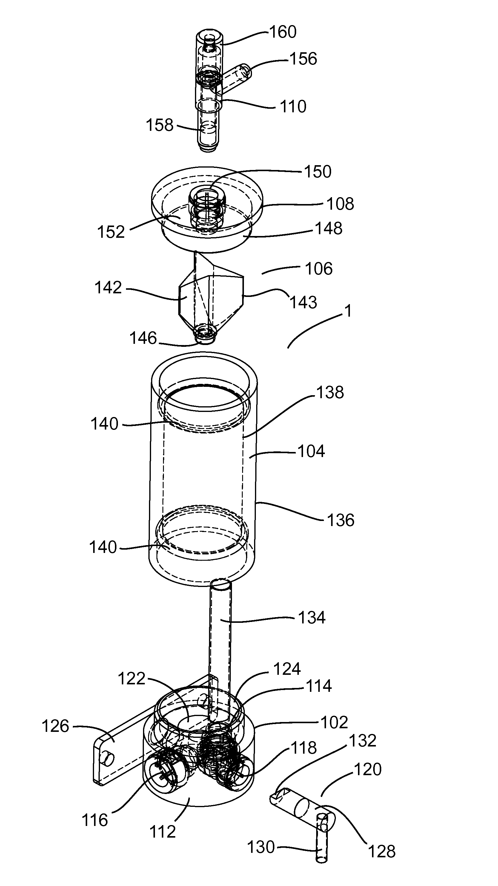
Figure 1 
Figure 2 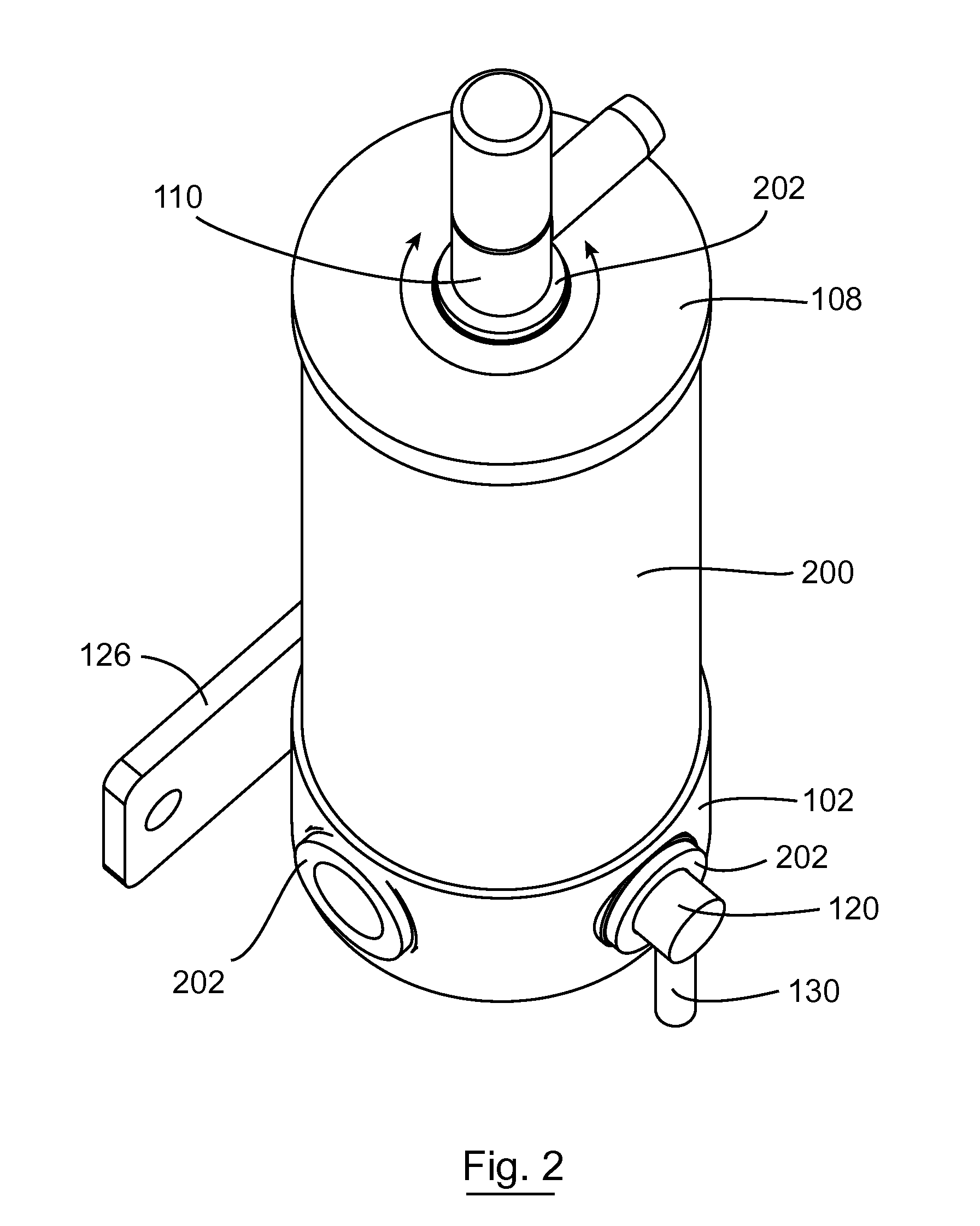
Figure 3
Abstract
Description
RELATED APPLICATIONS
[0001] The subject application is a U.S. National Stage application of International Application No. PCT / EP2008 / 067472, filed on 12 Dec. 2008, which claims the priority of Irish Patent Application No.: S2007 / 0898, filed on 12 Dec. 2007, the contents of which are herein incorporated by reference in its entirety.INTRODUCTION
[0002] The present invention relates to a flow control device for use in a supply line between a pressurized liquid container and a dispenser for the liquid, the flow control device comprising a chamber having an inlet for receiving liquid from the container; a base section comprising a chamber outlet for supplying liquid to the dispenser; a vent valve for venting gas from the chamber; a float valve comprising a float section and a seat section and movable to and from an open position wherein the chamber outlet is open to liquid flow and a closed position wherein the chamber outlet is closed to liquid flow; and a float valve opening mechanism.[000...
Examples
Embodiment Construction
[0018]The invention will now be more clearly understood from the following description of an embodiment thereof given by way of example only with reference to the accompanying drawings in which:—
[0019]FIG. 1 is an exploded view of the device according to the invention;
[0020]FIG. 2 is a perspective view of the device according to the invention;
[0021]FIGS. 3(a), (b) and (c) are side, perspective and top views, respectively, of the float valve;
[0022]FIG. 4 is a detail cross-section view of a portion of the device showing the inlet and outlet;
[0023]FIG. 5 is a detail cross-section view of a portion of the device, including the vent valve; and
[0024]FIG. 6 a detail cross-section view of a portion of the device showing the float lifter
[0025]Referring to the drawings, and initially to FIG. 1 thereof, there is shown a flow control device indicated generally by the reference numeral 1, comprising a substantially cylindrical base section 102, a substantially cylindrical tube forming a wall 104...