
Torsional vibration damper
a torsional vibration and damper technology, applied in the direction of fluid couplings, couplings, machines/engines, etc., can solve the problems of insufficient damping properties, complex construction of flywheels, and large circumference, and achieve excellent damping properties and simple structural design.
Patent Information
- Authority / Receiving Office
- US · United States
- Patent Type
- Patents(United States)
- Current Assignee / Owner
- Publication Date
- 2014-01-21
- Estimated Expiration
- Not applicable · inactive patent
Smart Images
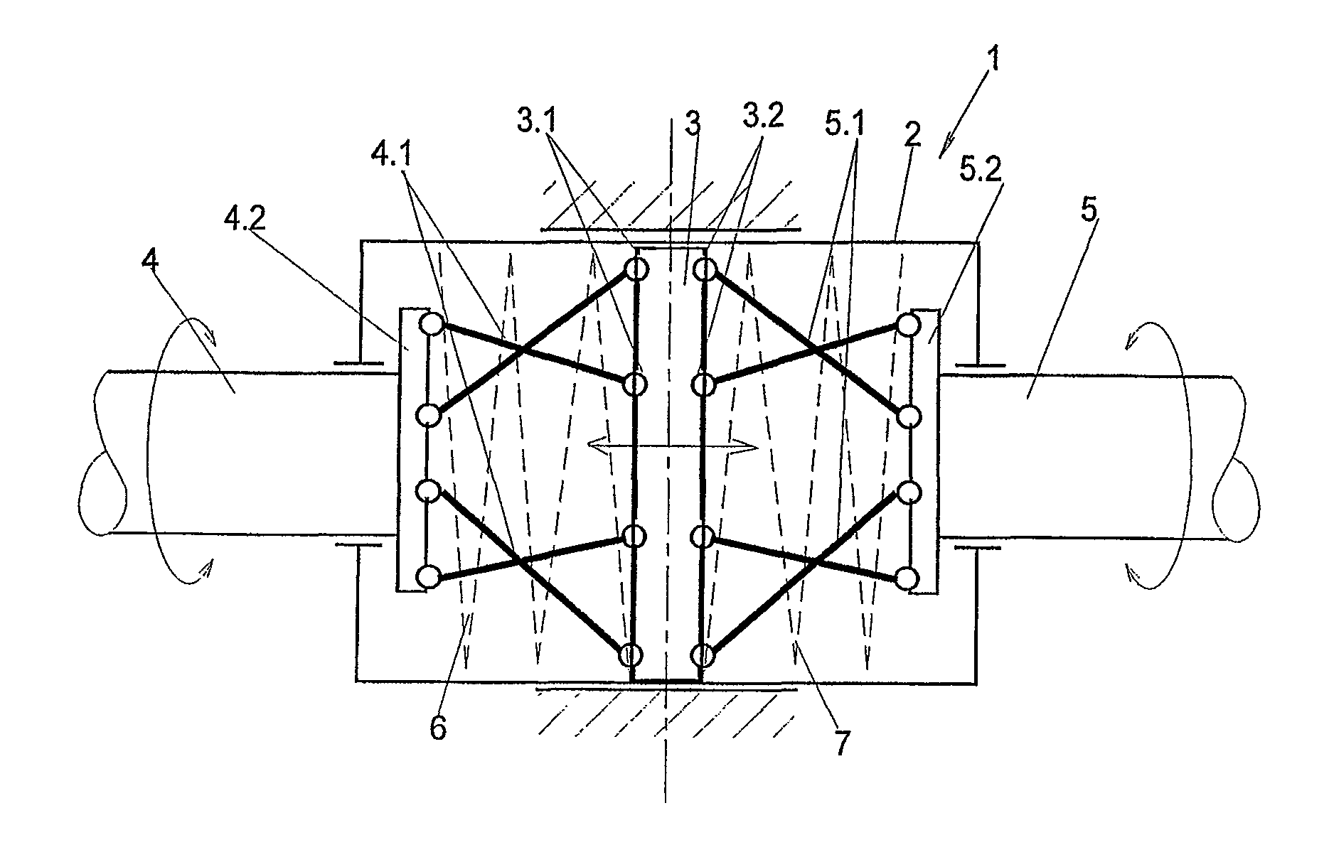
Figure 1 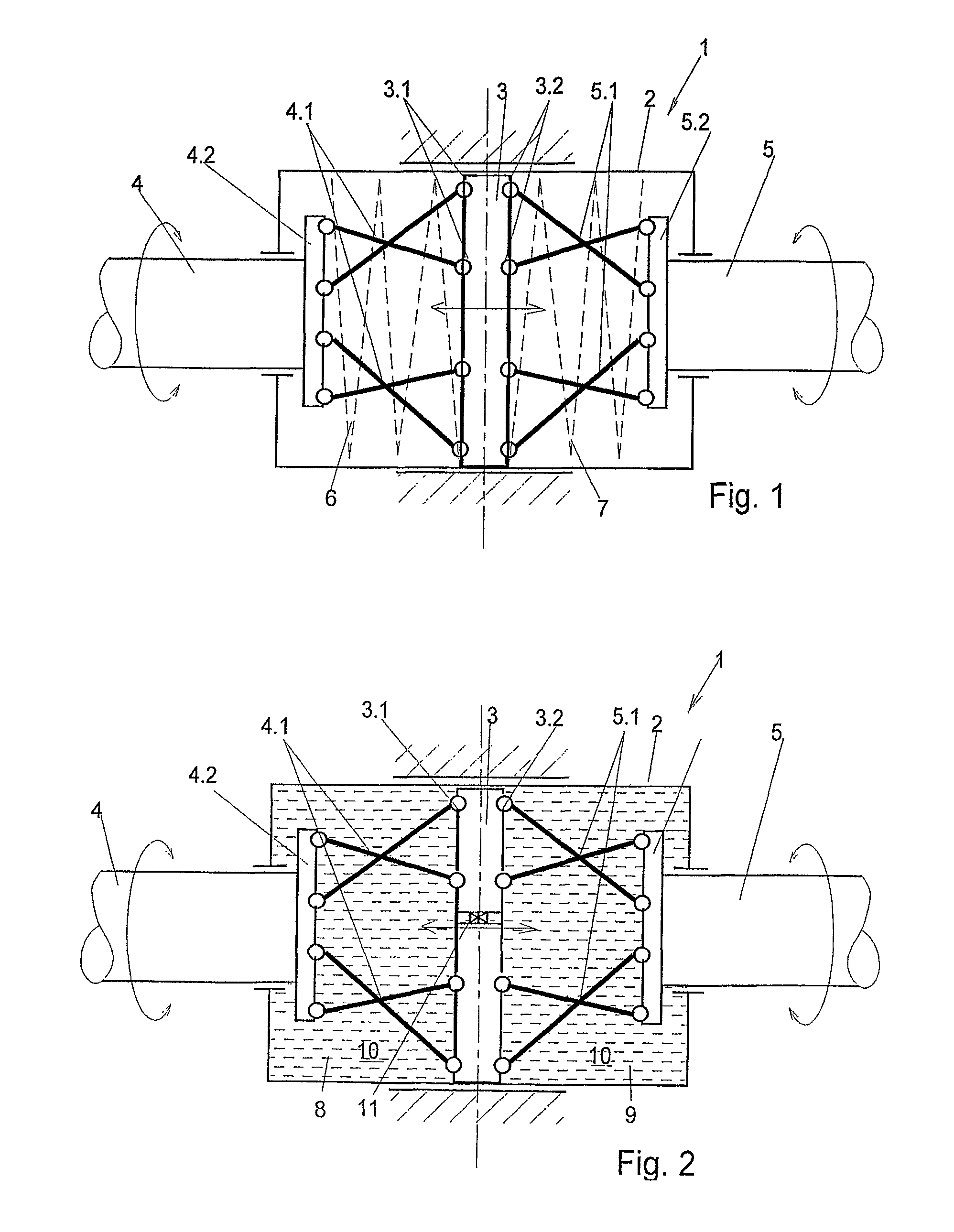
Figure 2 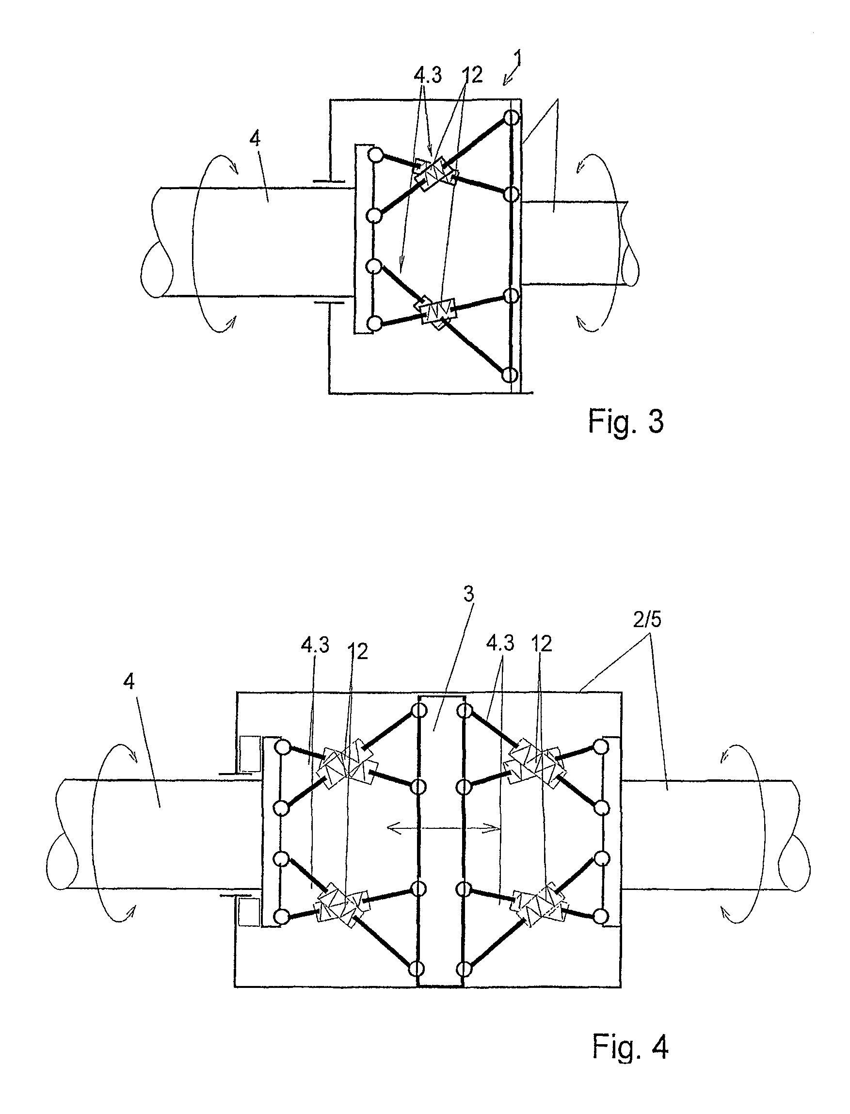
Figure 3
Abstract
Description
BACKGROUND OF THE INVENTION
[0001] The invention relates a torsional vibration damper, which is inserted between a driving system and a driven system and serves to damp the input and output vibrations and balances the torque variations.
[0002] There exist a plethora of torsional vibration dampers, wherein a driving element and a driven element are connected by a torsional spring (for example, DE 10 2005 037 996 B3) for torque transmission.
[0003] Furthermore, there exist systems, wherein a torsional vibration is damped by means of spring elements, which can be loaded in a radial or circumferential direction (DE 198 12 303 A1, DE 197 33 334 A1).
[0004] DE 32 28 673 A1 describes a torsional vibration damper with a laterally displaceable damping element. The torsional vibration damper, which is suited in particular for the clutch disk of a motor vehicle, has two damper parts, which can be rotated relative to one another about a common axis of rotation and which are coupled to one another by wa...
Examples
Embodiment Construction
[0031]FIGS. 1 and 2 show a torsional vibration damper comprising a damping element 1, which exhibits an axially displaceable coupling part 3 that is arranged in a housing 2. The housing 2 is mounted rigidly on the frame, and the coupling part 3 is arranged between a first element 4 in the form of a first rotary shaft and a second element 5 in the form of a second rotary shaft. In this case the first element 4 and the second element 5 can be rotated relative to each other. The first element 4 is connected to the coupling part 3 by way of the first rigid coupling elements 4.1, which are mounted in a rotatable manner, and the second element 5 is connected to the coupling part 3 by way of the second rigid coupling elements 5.1, which are mounted in a rotatable manner. The first coupling elements 4.1 are constructed in the form of ball bars and are rotatably mounted, on the one hand, with their ball-shaped ends in a first receptacle 4.2 of the first element 4 and, on the other hand, in a...