
Method and apparatus for removing peripheral portion of a glass sheet
a technology of glass sheets and peripheral parts, applied in the field of glass sheet periphery finishing, can solve the problems of affecting the overall yield, affecting the quality of glass sheets, so as to achieve less surface slippage in scoring, improve surface quality, and improve the effect of surface quality
Patent Information
- Authority / Receiving Office
- US · United States
- Patent Type
- Patents(United States)
- Current Assignee / Owner
- Publication Date
- 2014-06-24
- Estimated Expiration
- Not applicable · inactive patent
Smart Images
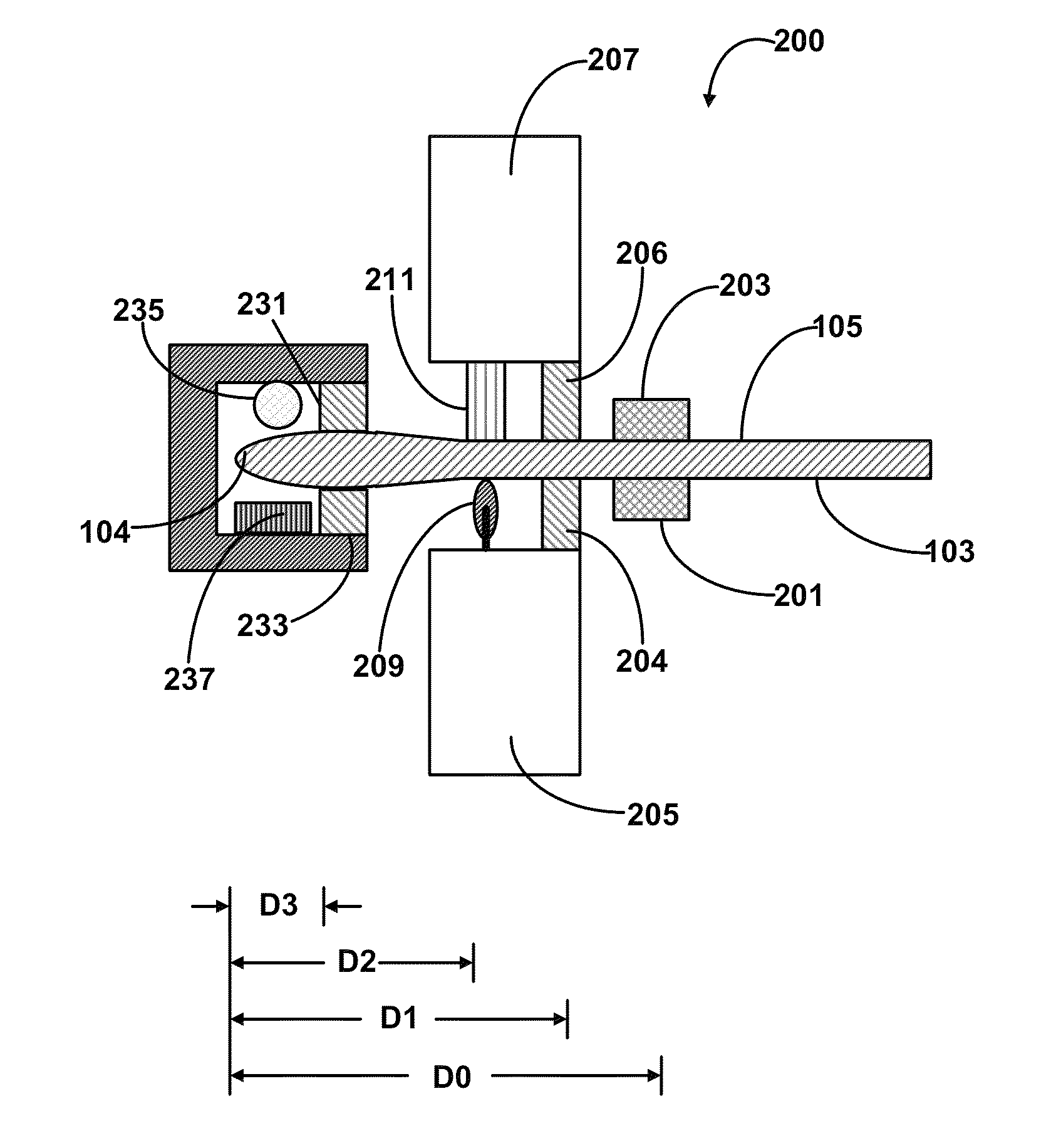
Figure 1 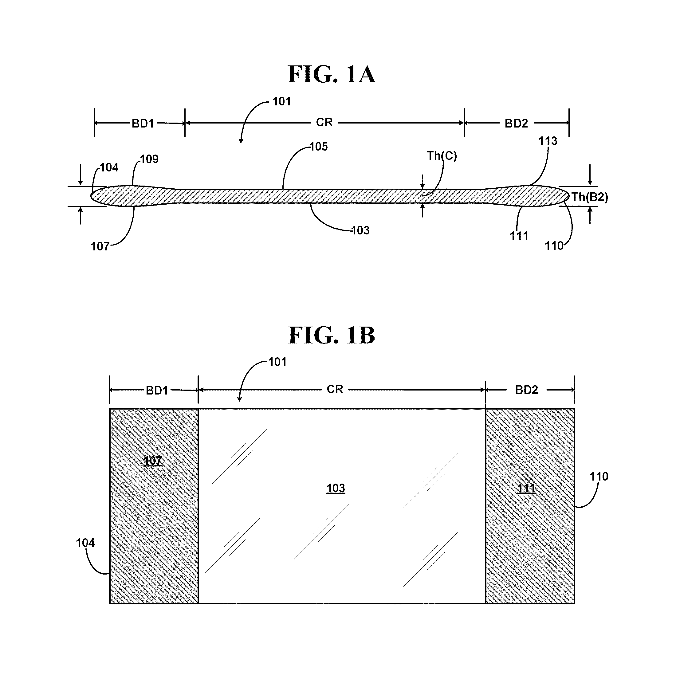
Figure 2 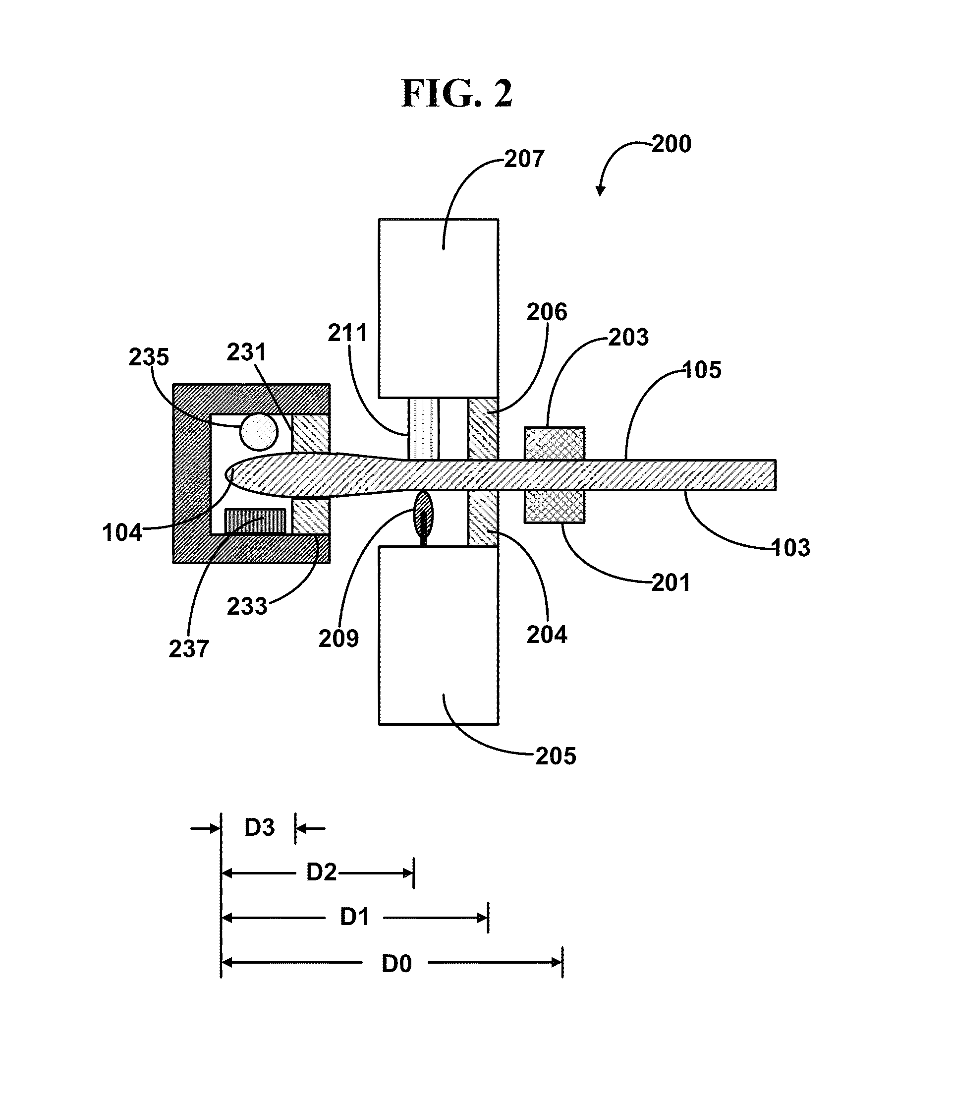
Figure 3
Abstract
Description
FIELD
[0001] The present invention relates to method and apparatus for glass sheet periphery finishing. In particular, the present invention relates to method and apparatus for removing a peripheral portion of a glass sheet. The present invention is useful, e.g., for removing the bead regions of a glass sheet formed from a down-draw process for use as glass substrates for displays.TECHNICAL BACKGROUND
[0002] Thin glass sheets have found use in many optical, electronic or optoeletronic devices, such as liquid crystal displays (LCD), organic light-emitting diode (OLED) displays, solar cells, as semiconductor device substrates, color filter substrates, cover sheets, and the like. The thin glass sheets, having a thickness from several micrometers to several millimeters, may be fabricated by a number of methods, such as float process, fusion down-draw process (a method pioneered by Corning Incorporated, Corning, N.Y., U.S.A.), slot down-draw process, and the like.
[0003] In many of the applica...
Examples
example 1
[0128]FIG. 2 schematically illustrates a cross-sectional view of one end of a glass sheet bead removing apparatus 200 in operation according to certain embodiments of the first and second aspects of the present disclosure. The other end, substantially symmetrical to the end illustrated, is not shown. The glass sheet shown in FIG. 1 is being secured by the two clamping arms 201, 203 of a clamp affixed to a suspension device (not shown) such as a vertical glass sheet suspension conveyor. Normally, the glass sheet is first engaged with the clamping arms 201 and 203 outside of the peripheral portion removing apparatus 200, and then moved into the apparatus 200 by the conveyor. Inside the peripheral portion removing apparatus 200, a first side edge restraining tower 205 comprising a first side edge restraining clamp strip 204 is located on the side of the first major surface 103 of the glass sheet, and a second side edge retraining tower 207 comprising a second side edge restraining clam...
example 2
[0130]FIG. 3 schematically illustrates a cross-sectional view of one end of a glass sheet bead removing apparatus 200 in operation according to another example. The other end, substantially symmetrical to the end shown, is not shown. In this example, the glass sheet shown in FIG. 1 is being secured by the two clamping arms 201, 203 of a clamp affixed to a suspension device (not shown) such as a vertical glass sheet suspension conveyor. Normally, the glass sheet is first engaged with the clamping arms 201 and 203 outside of the peripheral portion removing apparatus 200, and is then moved into the apparatus 200 by the conveyor. Inside the peripheral portion removing apparatus 200, a first side edge restraining tower 205 comprising a first side edge restraining clamp strip 204 is located on the side of the first major surface 103 of the glass sheet, and a second side edge retraining tower 207 comprising a second side edge restraining clamp strip 206 is located on the side of the second...
example 3
[0131]FIG. 4 schematically illustrates a cross-sectional view of one end of a glass sheet peripheral portion removing apparatus 400 in operation. The other end, being symmetrical, is not shown. As can be seen, compared to the apparatus 300 of FIG. 3, the apparatus 400 comprises suction cup(s) 215, but does not comprise the pushing bar 217. During operation, the first and second side edge restraining clamp strips 204 and 206 move towards each other once the glass sheet is positioned inside the apparatus 200, engage the glass sheet, restrain the portion of the glass sheet close to the bead region, and secure the glass sheet to enable the following steps. Once the glass sheet is clamped on both sides by the restraining towers (only one side shown in this figure), the heating bar 235 is turned on to preferentially heat the peripheral portion to a predetermined, desired temperature. Afterwards, a score-wheel 209, installed on the first side edge restraining tower 205, touches the first m...