
Motor vehicle with battery cooling system
a technology for motor vehicles and cooling systems, applied in batteries, hybrid vehicles, secondary cell details, etc., can solve problems such as toxic or flammable, and achieve the effects of improving the cooling capacity of passive cooling, facilitating integration in the motor vehicle, and improving the maintenan
Patent Information
- Authority / Receiving Office
- US · United States
- Patent Type
- Patents(United States)
- Current Assignee / Owner
- Publication Date
- 2016-11-08
Smart Images
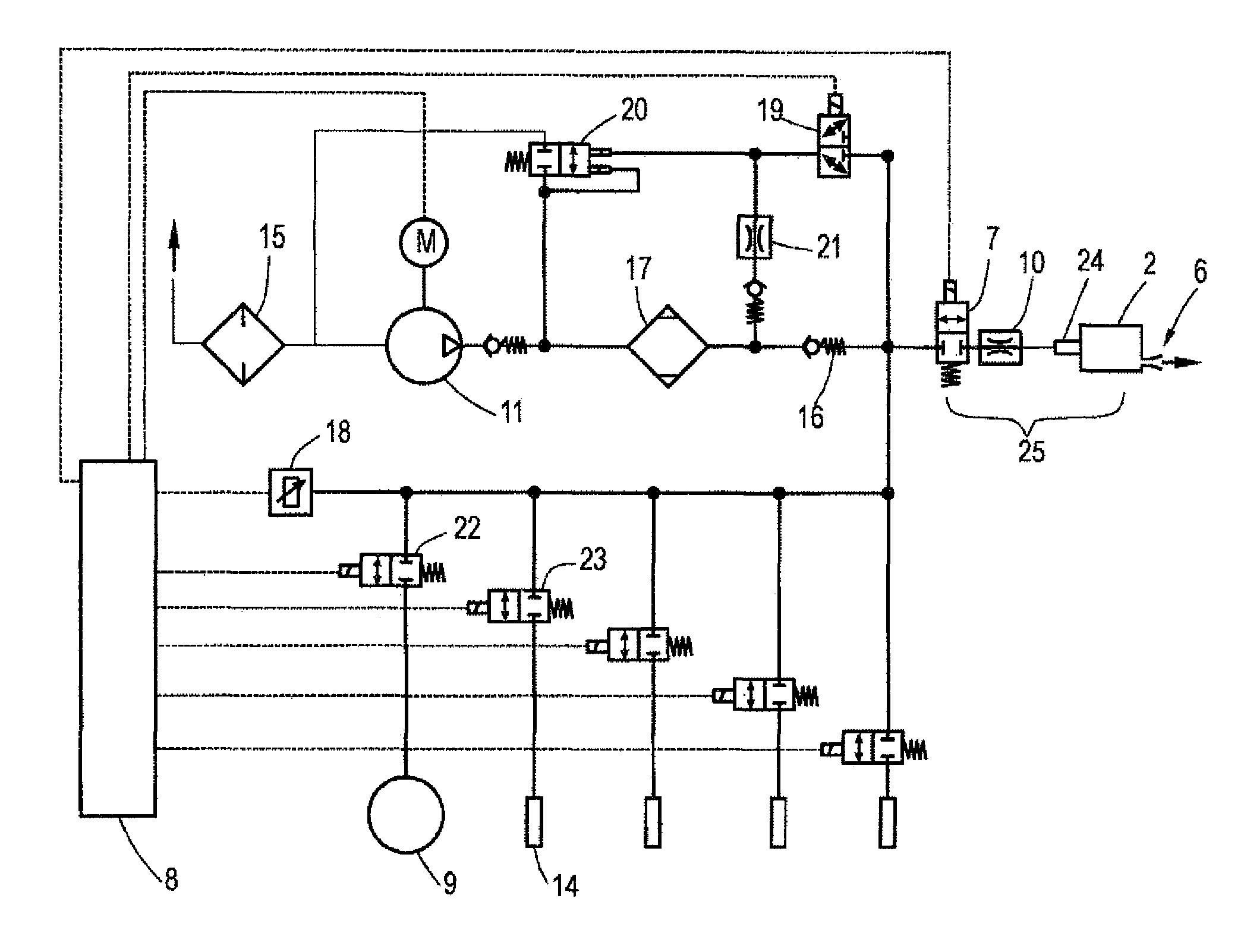
Figure 1 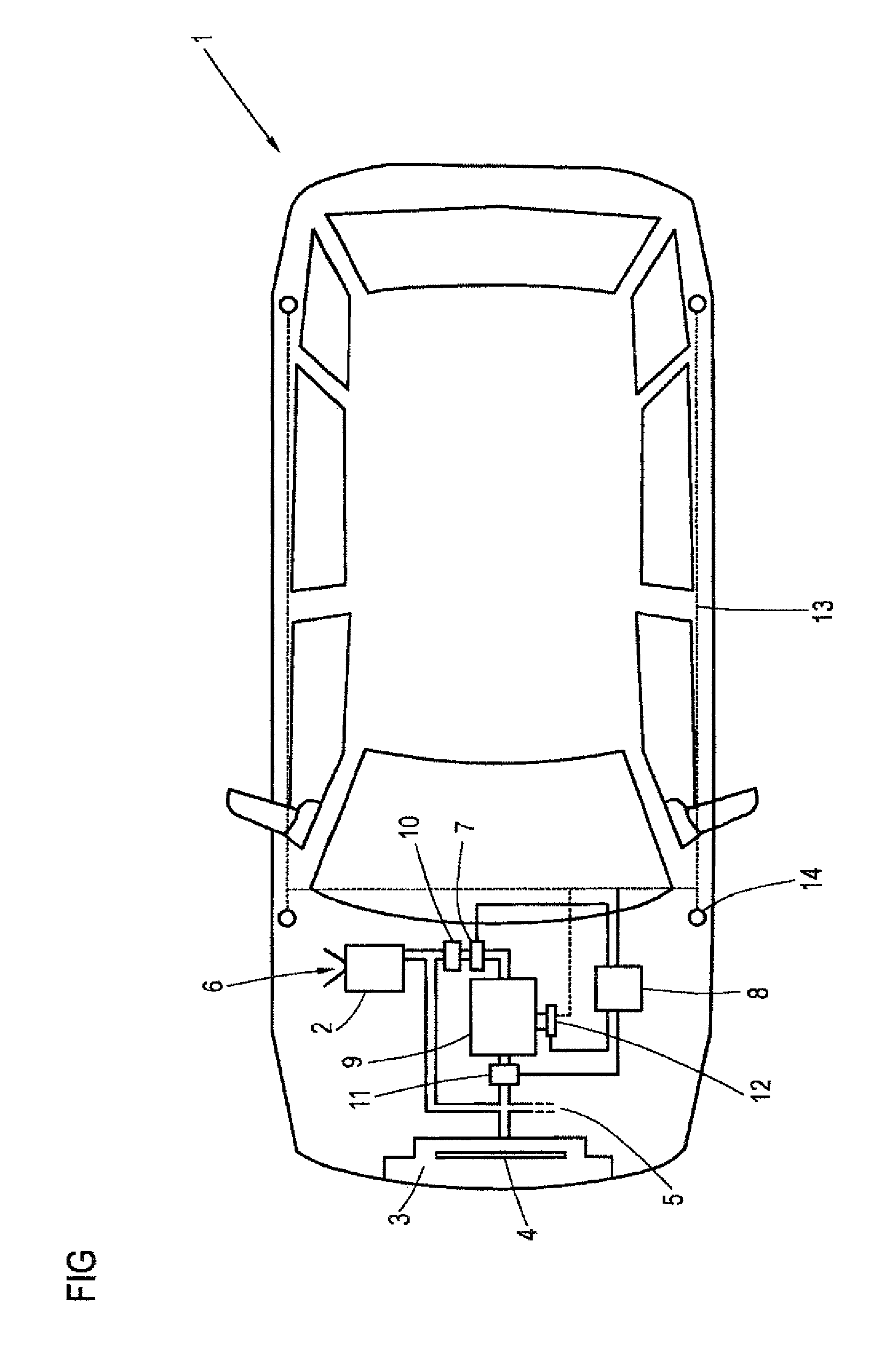
Figure 2 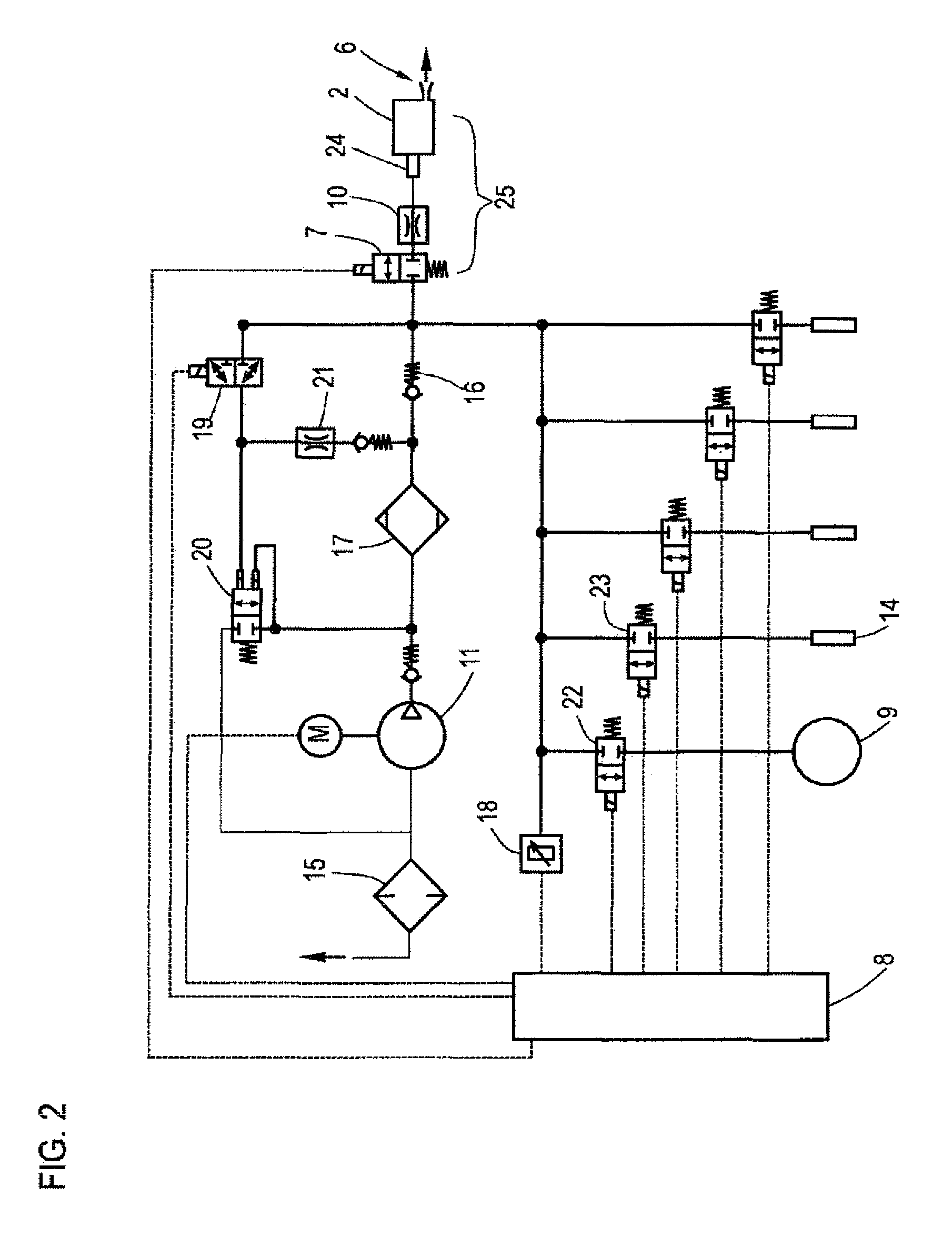
Figure 3
Abstract
Description
CROSS-REFERENCES TO RELATED APPLICATIONS
[0001] This application is the U.S. National Stage of International Application No. PCT / EP20131002420, filed Aug. 13, 2013, which designated the United States and has been published as International Publication No. WO 2014 / 029474 and which claims the priority of German Patent Application, Serial No. 10 2012 016 801.2, filed Aug. 23, 2012, pursuant to 35 U.S.C. 119(a)-(d).BACKGROUND OF THE INVENTION
[0002] The invention relates to a motor vehicle with at least a battery module having a cooling system.
[0003] Electric mobility is becoming increasingly important in particular from an environmental point. While purely electric vehicles still play a minor role and are particularly suitable for transport in inner cities, hybrid vehicles, especially mild-hybrid vehicles, become increasingly common.
[0004] In typical hybrid vehicles, a combustion engine and an electric motor are used. The electric propulsion portion is merely supportive in a mild-hybrid, i.e...
Examples
Embodiment Construction
[0028]FIG. 1 shows an exemplary embodiment of a motor vehicle 1 having a cooling system for a battery module 2. The battery module 2 can be cooled with compressed air, in addition to cooling by a conventional ventilation system 3 with a fan 4. In this case, the valve 7 is opened by the control device 8 and compressed air is supplied to the battery module 2 from the pressure accumulator 9. A throttle 10 which limits the flow of gas is also provided between the pressure accumulator 9 and the battery module 2. The gas is thereafter expanded and thus cooled in the subsequent pipe. The gas is supplied to the battery module 2 with overpressure, flows through the battery module 2 and is discharged at the exhaust outlet 6 back into the environment. The pressure accumulator 9 is part of the air suspension system and is connected to the pneumatic circuit 13 of the air suspension system by way of a valve 12. The pneumatic circuit 13 of the air suspension system can supply compressed air specif...